Tutorial
Starting with version 8.40, SIMPLIS will add support for user-defined digital devices implemented in C/C++ and distributed as a DLL. The following tutorial will walk the user through the process of creating a simple DLL-defined Digital Device in C using the built-in code generation tools.
Before beginning, it is recommended that you download the SIMPLIS Digital Development Kit that provides the header and support files for the tutorial example.
Getting Started with a DLL-defined Digital Device in SIMPLIS
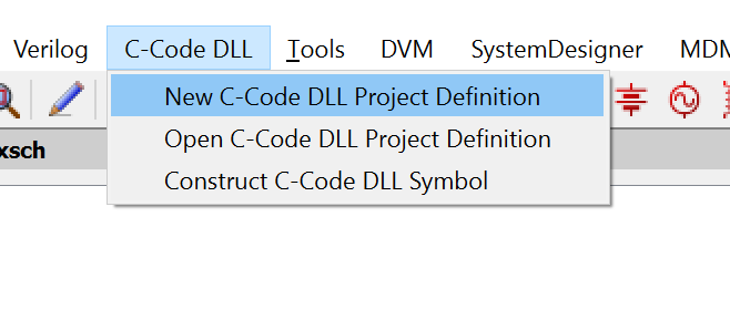
To begin a new DLL project, open your SIMPLIS schematic and choose .
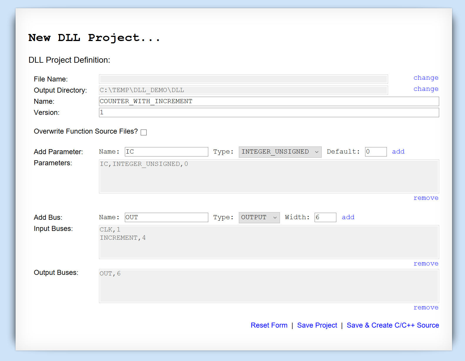
By default, the project's output files will be stored in the current working directory, typically the directory containing the most recent schematic.
Device Definition
- The only configurable parameters is an initial condition IC with a default of 0.
- The inputs will be a CLOCK pin and a 4-bit INCREMENT bus.
- The output will be a 6-bit OUT bus.
Code Generation
While it is perfectly acceptable to manually generate the required source functions to populate the DLL, SIMPLIS ships with a built-in code generation function that can create a working Visual Studio project from a device definition.
How to Use the Code Generation Feature
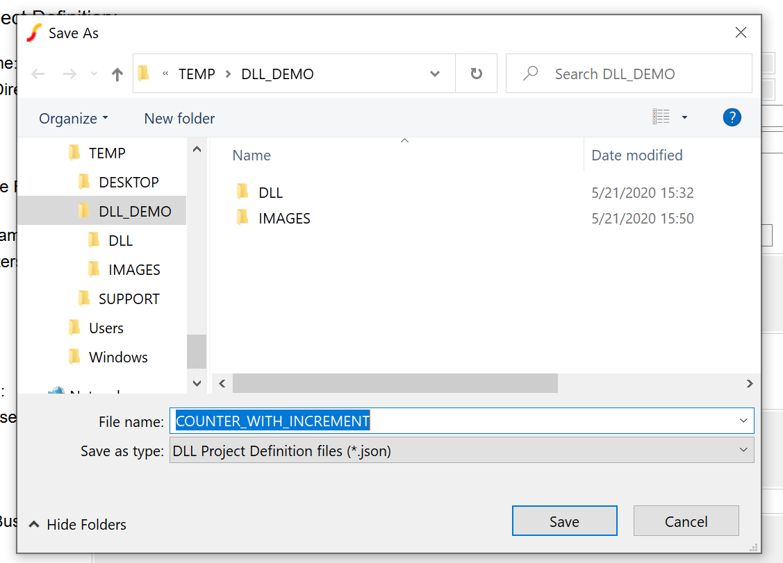
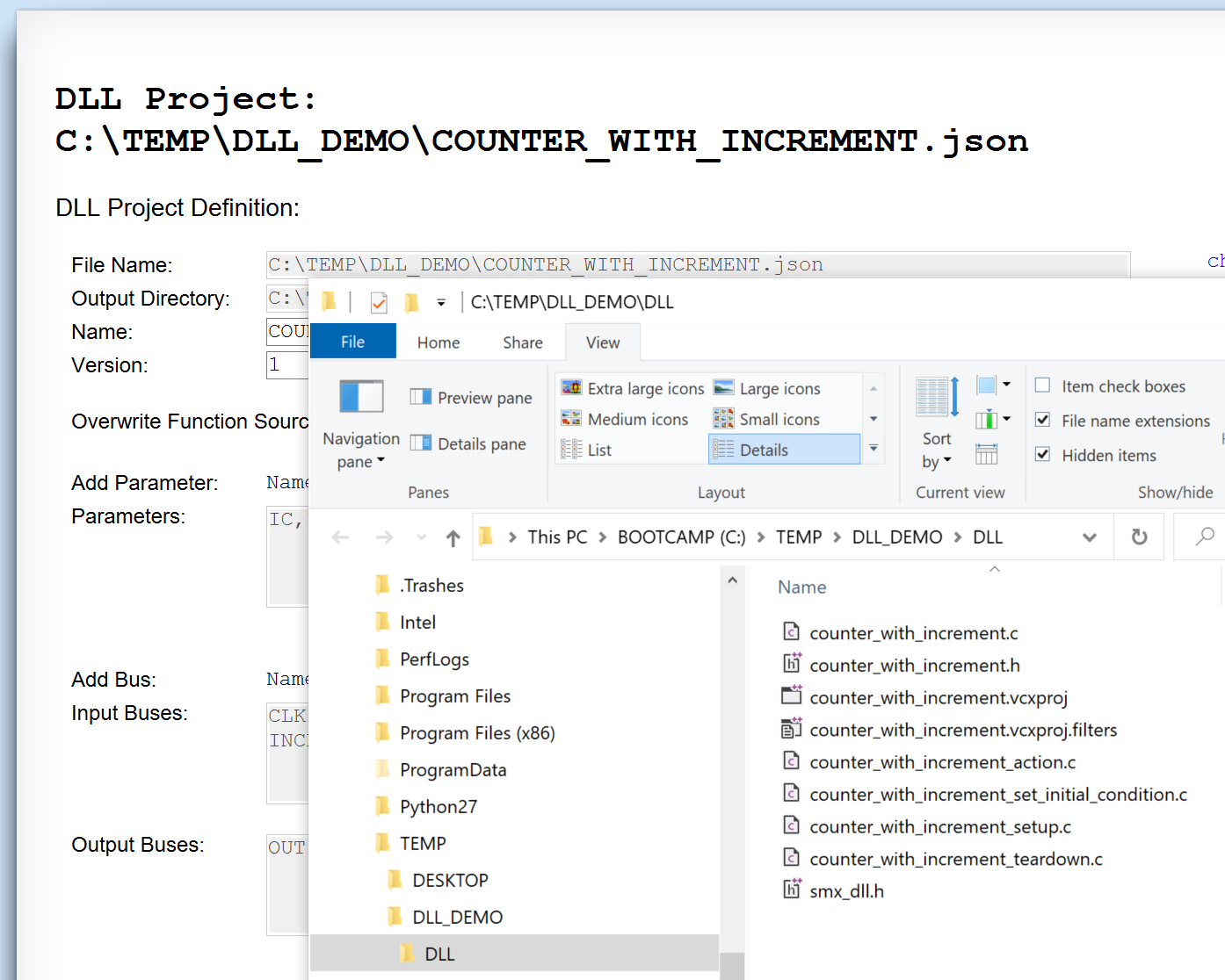
Choose Save & Create C/C++ Source. Since the project has not yet been saved, the save dialog will appear allowing the user to pick a filename for the project file.
Once the project is saved, the code generation routine will create source and project files in the output directory and open an Explorer window to that directory.
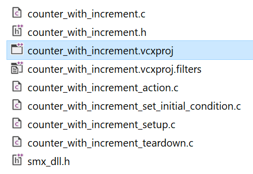
What Files are Generated
- The Visual Studio project files set to build a DLL containing the device definition:
- project name.vcxproj
- project name.vcxproj.filters
- The header file defining the interface to the SIMPLIS simulator:
- smx_dll.h
- The header file and main source file for the device definition:
- project name.h
- project name.c
- The source files for each of the four core functions that the DLL-defined digital device must implement:
- project name_setup.c
- project name_set_initial_condition.c
- project name_action.c
- project name_teardown.c
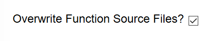
Unless the "Overwrite Function Source Files" box is checked, these files will not be overwritten on subsequent presses of the Save & Create C/C++ Source option.
Compiling the DLL
The code generation process creates a ready-to-build Visual Studio project file for your DLL-defined digital device. You can download Visual Studio from Microsoft for evaluation purposes if your organization does not already have a license.
The features required to build SIMPLIS DLL-defined digital devices are found in all three versions of Visual Studio: Community, Professional and Enterprise. Students and individual contributors should find the Community edition sufficient to their needs, members of larger organizations should choose an appropriate license for their situation.
Building the Project in Visual Studio
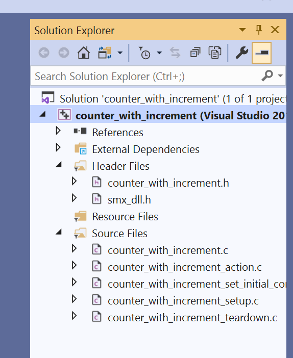
Open the .vcxprj file in Visual Studio.
Expand the Solution Explorer window to show the source and header files that are a part of the project.
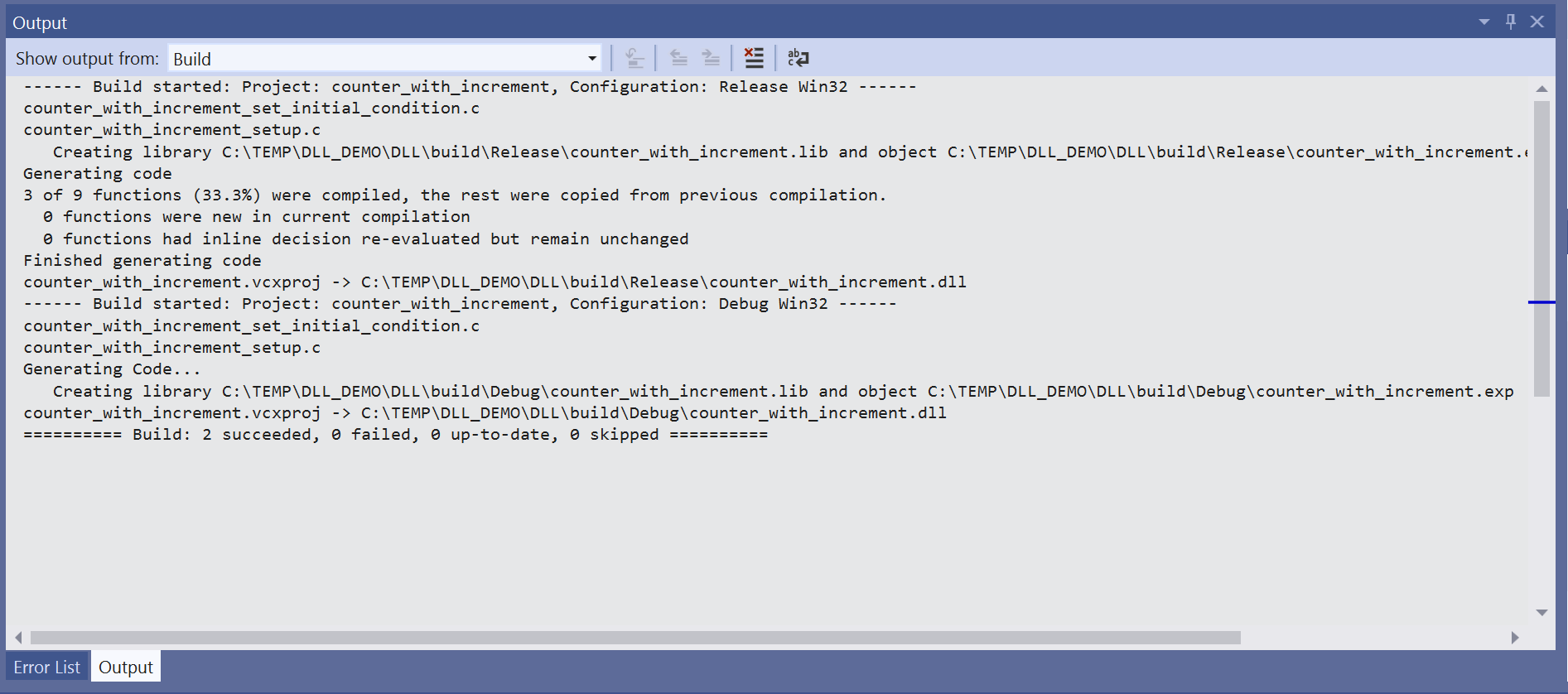
From the menu, choose Build | Batch Build... and select both the "Debug" and "Release" versions to build.
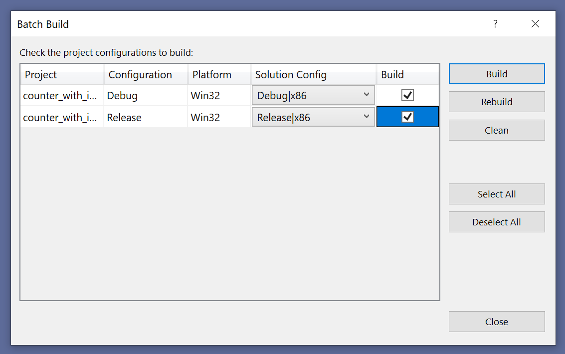
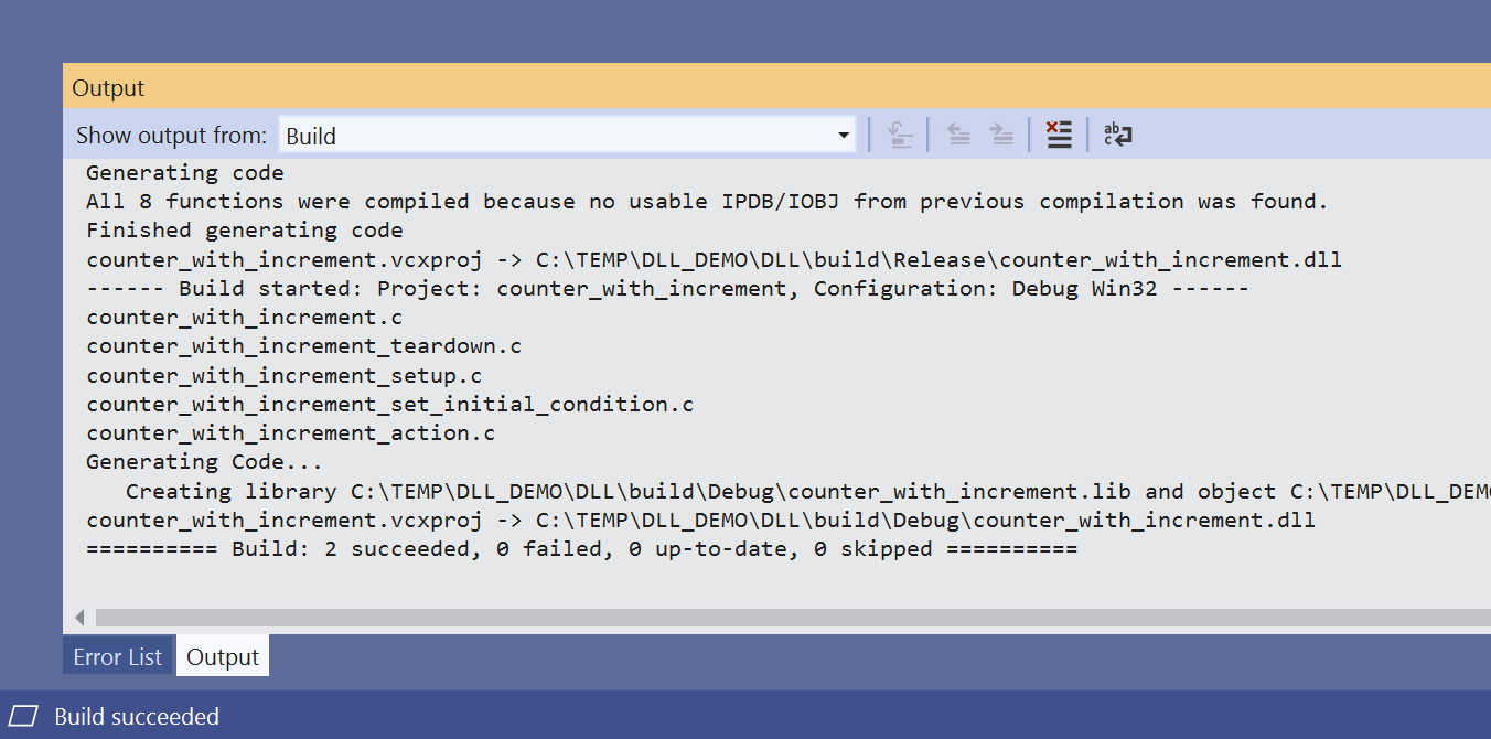
When the build successfully completes, Visual Studio's console will show that both the "Debug" and "Release" .dll files have been created.
Creating a Symbol and Placing it on the Schematic
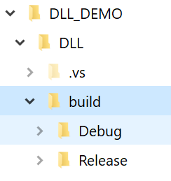
By default, the output files are placed in subdirectories of the automatically created "build" folder.
Returning to the schematic, you can now place an instance of the newly created DLL-defined Digital Device on the schematic. From the menu, choose .
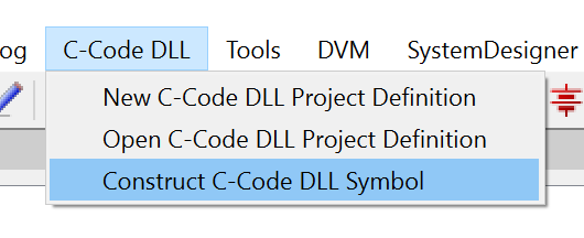
Using the resulting file selection dialog, select the newly built "Release" .dll file found in the "build/Release" directory and hit "Open".
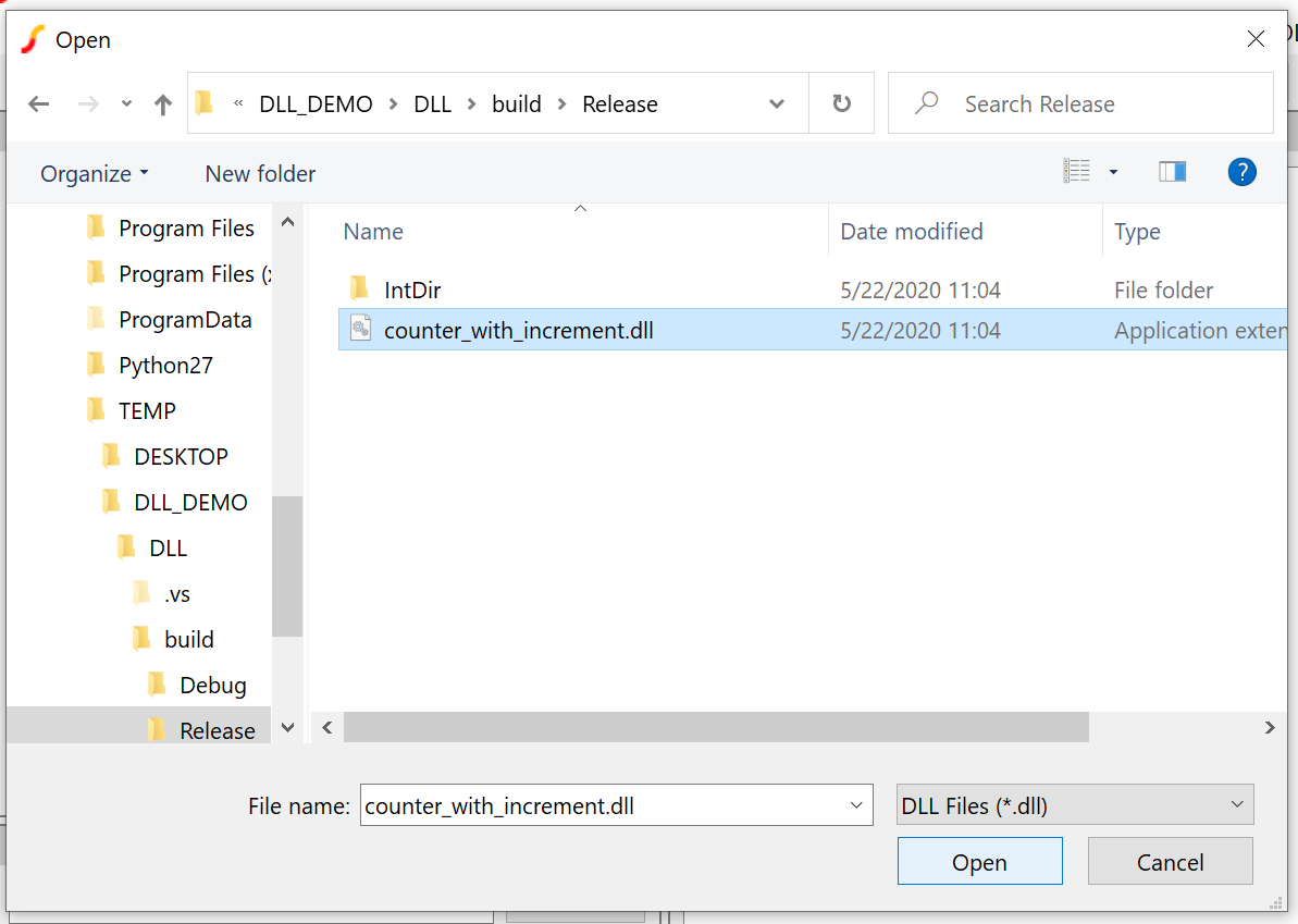
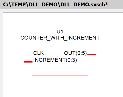
At this point, the system loads the DLL file and gets a list of the devices that are defined in it. Since this example only has one device definition, that definition is automatically selected and a symbol is created for it. Place it on the schematic.
Configuring a Test Schematic
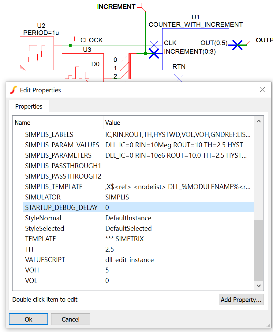
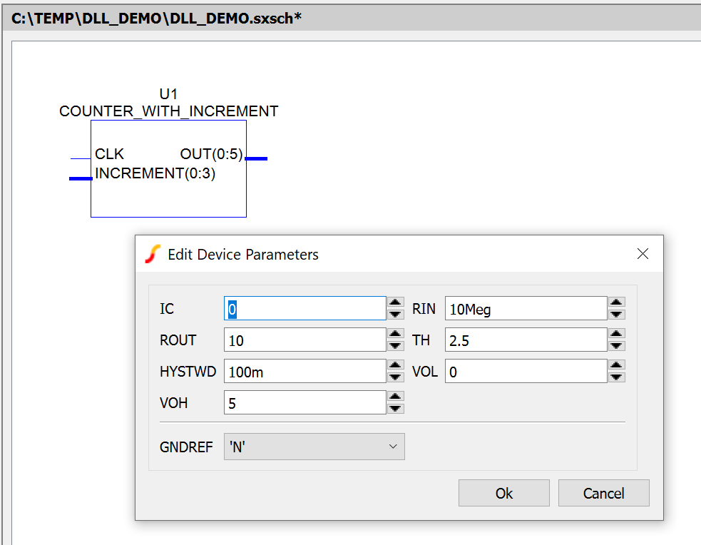
Double clicking the symbol displays the automatically generated edit dialog, with our only configurable parameter, IC.
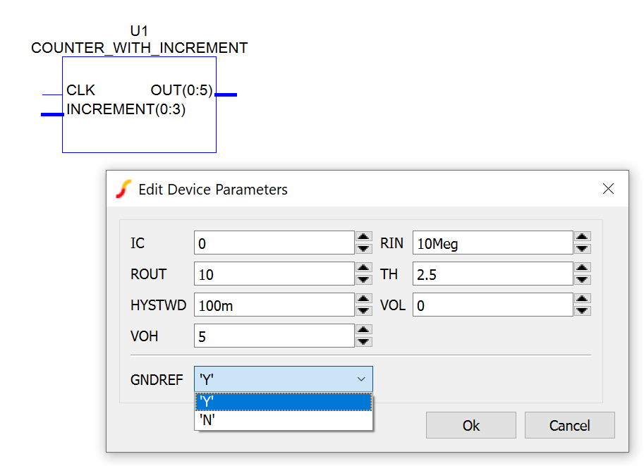
Since our circuit will only contain digital devices, set the "GNDREF" property to 'Y' to enable a GND pin for the device.
To test our device, add a digital pulse source with a PERIOD of 1u, PULSE_WIDTH of 500n and a START_DELAY of 250n. Wire up a 4 bit digital signal source to the INCREMENT bus of the DLL-defined Digital Device.
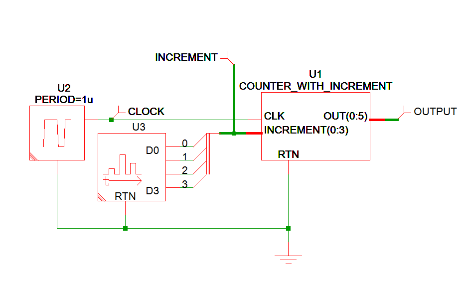
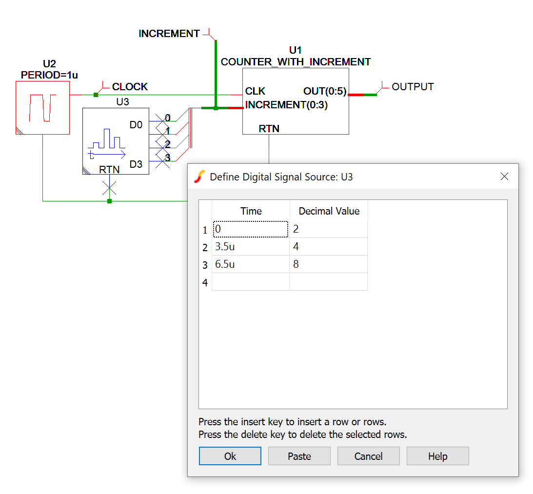
The signal definition for the digital signal source is setup to step through a small series of INCREMENT values as defined in the table below.
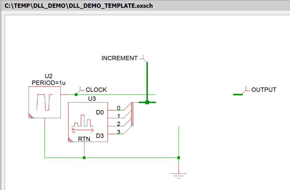
There is a template schematic provided with the tutorial materials that has all of the surround circuitry and probes pre-configured, ready for placing the DLL-defined Digital Device symbol.
Using the Device in Simulation
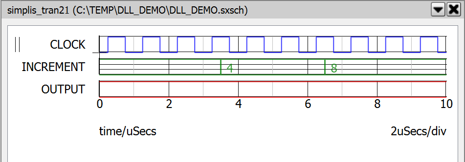
By default, all of a device's outputs are set to X, so when the simulation is run, you will see the following waveforms.
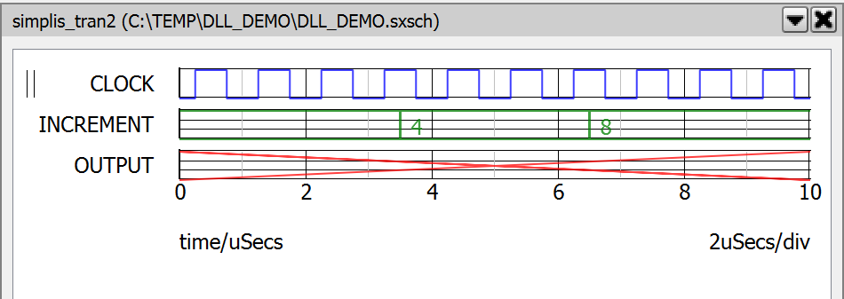
This is as far as a user can get without writing any code as there is no way for the code generation feature to guess what you want the output of the device to do during simulation.
Customizing the Code: Initial Conditions
-
setup
-
assign default pointers: Call a pre-defined routine to populate a struct that contains pointers to the input and output buses as well as the values of the parameters passed in by the user.
-
allocate managed user storage: The example will use an 8bit unsigned integer to hold the current value of the counter. By using managed user storage, the code will always have access to the correct, most recent value assigned to it, even if the simulator has to roll back.
-
-
set_initial_condition
-
assign initial condition of the output: In the cases where a device has only one output bus and there is an unsigned integer parameter called IC, a pre-defined routine can be called to copy that user value to the output.
-
assign initial value to the managed user storage: The user's IC parameter should also be assigned to the managed user storage so that when the device first wakes up, it knows its correct starting value.
-
Testing the Initial Conditions
Customized versions of each of the relevant source files can be found in the customized subdirectory in the example package. To start with, first modify only the setup and set_initial_condition routine. Perform another batch build, which should show that those files were re-compiled.
Run the simulation, you should see that the output is no longer unknown, it's fixed at the initial condition value, the default of which is zero.
Customizing the Code: Action During Simulation
-
action
-
look for a positive edge on the CLK pin: For this example, the counter is assumed to trigger on a positive edge of the CLK pin.
-
convert the INCREMENT bus: Call the built-in "read_bus" function to convert the inputs of the pins of the INCREMENT bus to an 8bit unsigned integer.
-
determine new counter value: Add the INCREMENT value to the stored output and assign it to the managed storage value.
-
write new value to OUT bus: Call the built-in "write_bus" function with a fixed output delay of 1ns.
-
-
teardown
- No customization required as you aren't allocating any memory outside of the provided managed and unmanaged storage options.
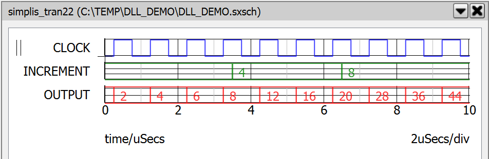
Perform another batch build, then run the simulation. You should see that the device is now counting up while appropriately using the value of INCREMENT.
Debugging During Development
- breakpoints
- step commands (step into, out of and over functions)
- variable inspection and watch
Prerequisites
- the "Debug" version of the DLL should have a debug breakpoint set in the function you wish to debug
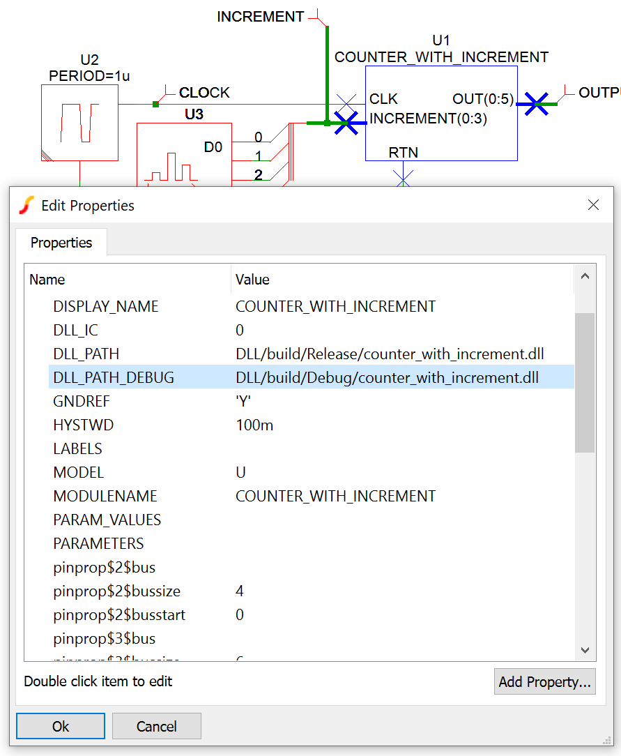
- the symbol for the DLL-defined Digital Device should point its DLL_PATH_DEBUG property to the "Debug" version of the DLL
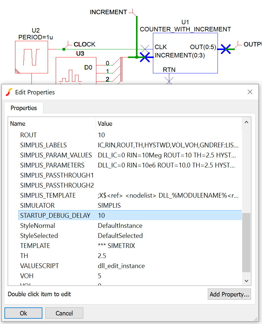
- the STARTUP_DEBUG_DELAY property should be set to a non-zero value
Setting a Debug Breakpoint
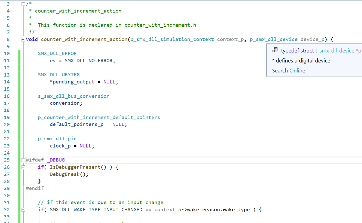
DebugBreak()function is used. In the below example, a breakpoint is added to the action function. There are a few important things to note:
- wrapping the block in the
#ifdef _DEBUG
ensures that the code is not present in the "Release" version of the DLL. Using theDebugBreak()
function in a "Release" DLL can have unwanted side effects for the user and should be avoided. - wrapping the call in the
if( IsDebuggerPresent() )
block ensures that the code only breaks when the debugger is attached.
Setting the Path to the Debug DLL
When creating the symbol for the first time, the instructions above recommended selecting the "Release" version of the DLL for the symbol. This ensures that users who do not have debug libraries installed are able to simulate with the device. Since the "Release" version does not have the necessary symbols to allow for debugging, the system requires some additional information in order to load the "Debug" DLL during development.
If the instructions above were followed, the batch build ensures that both "Release" and "Debug" versions of the DLL are built at the same time, and are kept up-to-date with each other. When both versions are present at the time the symbol is created, and the path to the "Debug" DLL can be found by substituting the first instance of "Release" with "Debug" at symbol creation time, the DLL_PATH_DEBUG property will be automatically populated. Right click the symbol on the schematic, and look for that property. If it is not populated, you should set its value to the relative path to your "Debug" DLL.
Setting a Startup Debug Delay
DebugBreak()is wrapped in the
if( IsDebuggerPresent() )block, just setting the path to the "Debug" DLL is not sufficient to cause the breakpoint to be tripped, the debugger needs to be attached. While it is possible to attach the debugger mid-simulation, it would make it difficult to debug the setup and set_initial_condition functions. To address this, it is required to specify non-zero value for the STARTUP_DEBUG_DELAY property in order to get. This value is an integer representing the number of seconds that SIMPLIS will pause before launching the first setup function for any DLL-defined Digital Devices present in the circuit. When If multiple devices specify different values, the largest value will be used.
When first getting used to the Visual Studio interface, it may be helpful to specify a 20 or 30 second startup delay, but once it becomes more familiar, 10 seconds is typically long enough to switch focus and attach the debugger.
Attaching the Debugger
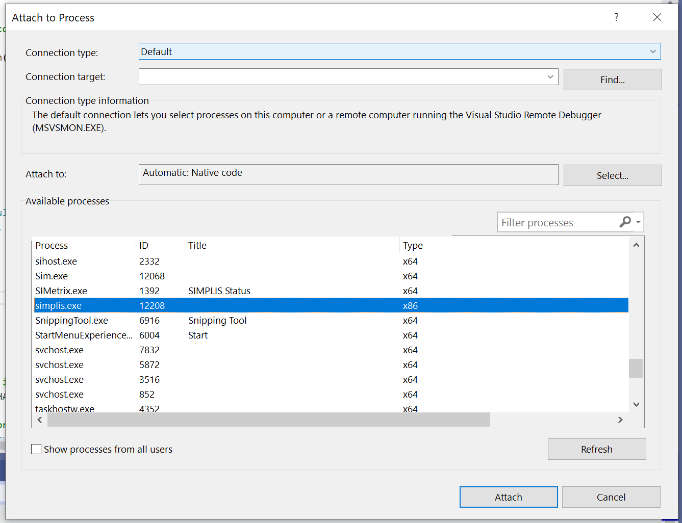
While SIMPLIS is paused, switch focus to Visual Studio. From the menu, choose Debug | Attach to Process... When presented with the list of running processes, choose simplis.exe and click "Attach". Once attached, you can step through the code line by line, or run up until any arbitrary breakpoint you set.
Disabling the Debug Version
The "Debug" version of the DLL specified in the DLL_PATH_DEBUG property will only be used by SIMPLIS if that property is not empty, and the STARTUP_DEBUG_DELAY property is set to a value greater than zero. To disable the "Debug" version without clearing the path, just set the STARTUP_DEBUG_DELAY back to zero. This will re-enable the "Release" DLL.