1.0 Introduction: What is DVM?
The SIMetrix/SIMPLIS DVM (Design Verification Module) automates the following tasks:
- Executes multiple user-defined simulation tests.
- Makes scalar measurements and checks those measurements vs. design specifications.
- Generates a comprehensive summary report with the following information:
-
- Pass/fail status for individual tests
- Links to tables of measured scalar and specification results
- Links to graphical data for individual tests
- Links to SIMetrix/SIMPLIS graph files which contain the raw simulation data
DVM has built-in testplans, including versions prepared for DC/DC and AC/DC converters. DVM also supports user-defined testplans that include configuration of both SIMetrix and SIMPLIS simulation engines, analysis directives, component values, and other test conditions. A properly configured schematic can also take advantage of the sensitivity and worst case analysis features of DVM.
In this topic:
How DVM Works
To run DVM on a schematic, you need the following:
- A schematic prepared to run a DVM testplan.
- A testplan compatible with the schematic.
Preparing a working schematic for use with DVM involves the following:
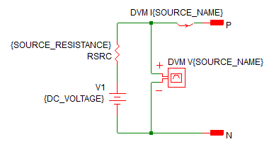
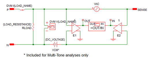
- Adding a DVM input source and output load symbol.
- Adding a DVM control symbol.
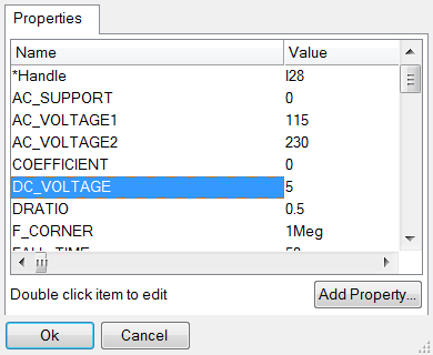
- Entering the design specifications for the input voltage and output load into the DVM control symbol.
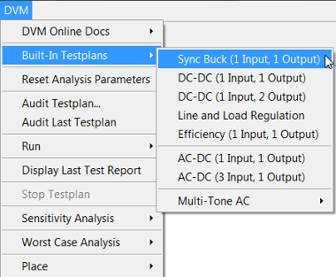
At this point you can select a built-in testplan to run, as shown below.
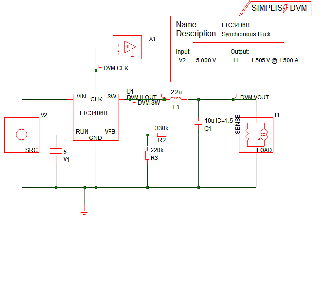
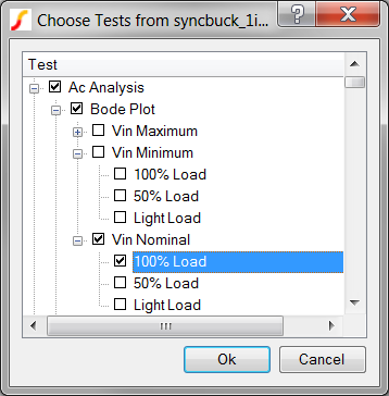
The schematic above is taken from the DVM Tutorial. This circuit uses the special DVM source and load symbols which allow you to run the Built-In Sync Buck testplan. This testplan has tests for both transient and AC analyses, and for this example, the Bode plot test is used. This test measures the converter loop stability at the nominal input voltage and 100% full load values. These symbolic values are explained in the Symbolic Values topic.
| *?@ Analysis | Objective | Source | Load | Label |
| Ac | BodePlot(OUTPUT:1) | Source(INPUT:1, Nominal) | Load(OUTPUT:1,100%) | Ac|BodePlot|Vin Nominal|100% Load |
DVM Slideshow
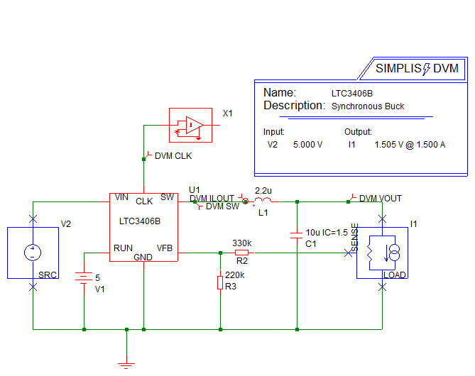
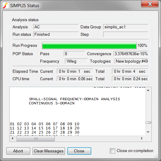
The following slideshow illustrates the sequence of actions that DVM takes as it executes a single test from the Built-In Sync Buck testplan. The test used for this example is the same BodePlot test described in the previous section.
- You can pause the slideshow by moving the mouse cursor over the images.
- To go forward or back one slide, click the arrow links that appear when you mouse over the slideshow.
- Each slide number is shown in the bottom right-hand corner. You can jump to a particular slide by clicking one of the gray squares at the bottom on the image. The current slide is indicated by the white square.
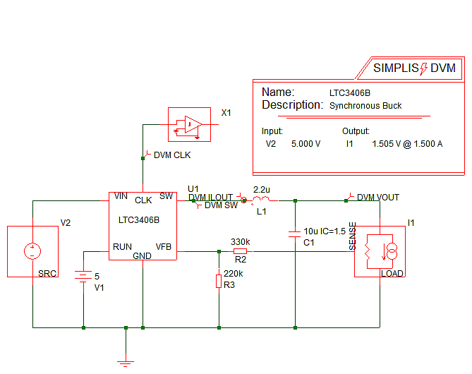
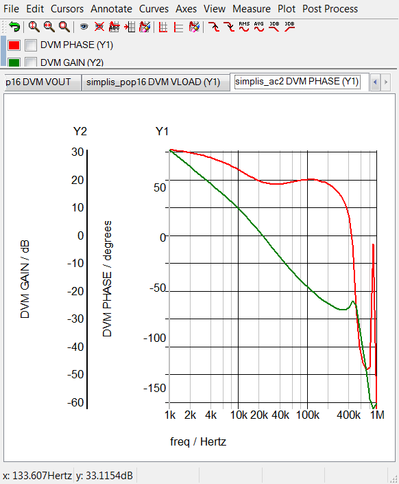
Although the slideshow illustrates actions that DVM takes for a single test from the built-in testplan, the DVM functionality encompasses much more than just Bode plot testing. Built-in testplans for one-input, one-output and one-input, two-output DC/DC converters are provided and include a full suite of tests that designers often run on power supplies, including Step Line, Step Load, Input and Output Impedance, and more.
Additionally a full suite of AC/DC tests are available in the one-input, one-output and thee-input, one-output Built-In AC/DC testplans.
For a full list of available tests, see the the following topics:
DVM also provides the ability to customize testplans to suit any design. For details about how to customize test plans, see Customizing Testplans in the DVM Tutorial.
Test Report
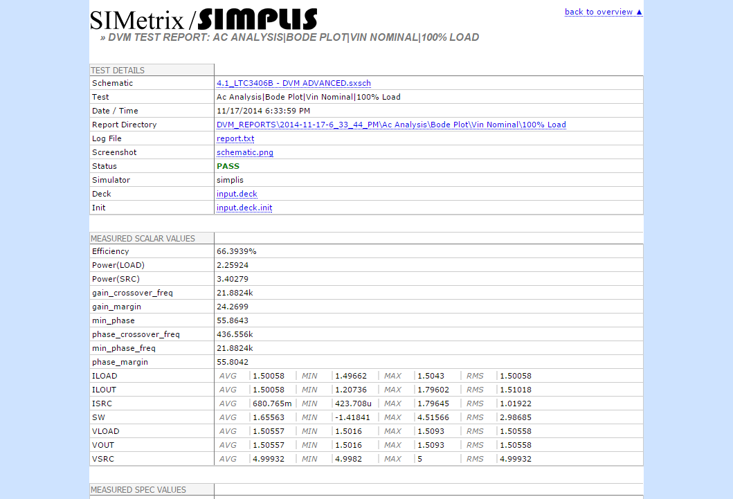
Upon completion of the test suite, the DVM generates an overview report that gives you a high-level view comparing the circuit performance with its specifications (Full Power Assist only). From the overview report, you can drill down to any individual test result and examine measured results, static waveform graphics, and even the raw waveform data itself. The Bode plot test report is shown below.
Text Conventions
The following text conventions are designed to help you scan the content:
- Bold text usually indicates something that you are to select on the screen or to type on the keyboard. File names are also in bold.
- Result information appears in green italic text to indicate what
should occur after you complete the instructions in a numbered step.Result: Green italic text ...
- Menu selections appear with a > separating the menu items. For
example, indicates the following instruction:
From the menu bar, click File and then select Save Schematic .
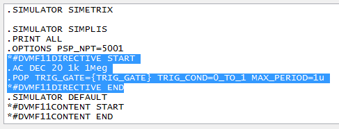
- A monospaced font indicates code that you enter in a testplan.
- The following table lists the default colours used by the built-in
script editor in SIMetrix/SIMPLIS.
Script Editor Colours
Item Colour Hex Code Keyword #0C69FF Command #FF0000 String #800000 Double Quote String #800080 Comment #008080 Function #008000 BIScript #FF00FF Note: Blue text indicating a function in the scripting language is not a hyperlink. All hyperlinks are in blue but are also underlined.To change the default colours in the Script Editor, follow these steps:
- In the SIMetrix/SIMPLIS toolbar, click the "gear" icon (
 ). Result: The Options/Preferences dialog opens.
 - Widen the window to show all the tabs, and then click the Text Editors tab
- From the Item column select the editor that you want to view or change.
- In the Colour column, double click any color and change it in the Choose Colour dialog box.
- Click Ok to dismiss the Choose Colour dialog and then click Ok again to dismiss the Options/Preferences.
- In the SIMetrix/SIMPLIS toolbar, click the "gear" icon (
Additional Documentation
For additional information, see the following: