2.2 SIMPLIS MDM Overview
In this section you open the main window of the SIMPLIS Magnetics Design Module (MDM) for the first time and go over what each part of the SIMPLIS MDM interface does.
In this topic:
What You Will Learn
In this topic, you will learn the following:
- How to start and open SIMPLIS MDM.
- How to open and view MagDB, the database of standard parts included with SIMPLIS MDM.
- How to open and use the MDM Status Window.
- What each tab of the main SIMPLIS MDM window is for.
2.2.1 Start MDM and Open the Main SIMPLIS MDM Window
By default, in order to shorten the start-up time of the program, SIMPLIS MDM is not started automatically when you start SIMetrix/SIMPLIS. MDM will therefore start when you first attempt to use it. This will last a few seconds, and then SIMPLIS MDM will continue to run in the background until you close SIMetrix/SIMPLIS. In order to start MDM, follow these steps:
- Optionally: close the Waveform Viewer that is displaying the results of the simulation you ran in the previous section.
- Double click the L1 symbol. Result: The Edit Multi-Level PWL Inductor dialog opens.
- Under Model level, select the Level 2 radio button. Result: The Edit Multi-Level PWL Inductor dialog changes to display Level 2 model parameters.
- Click the Create with SIMPLIS MDM... button. Result: The SIMPLIS MDM splashscreen, shown below, should appear for a few seconds, indicating that MDM is loading.
 Result: When the splash screen disappears, the main SIMPLIS MDM window, opened to the "Core" tab, will appear, as shown below.
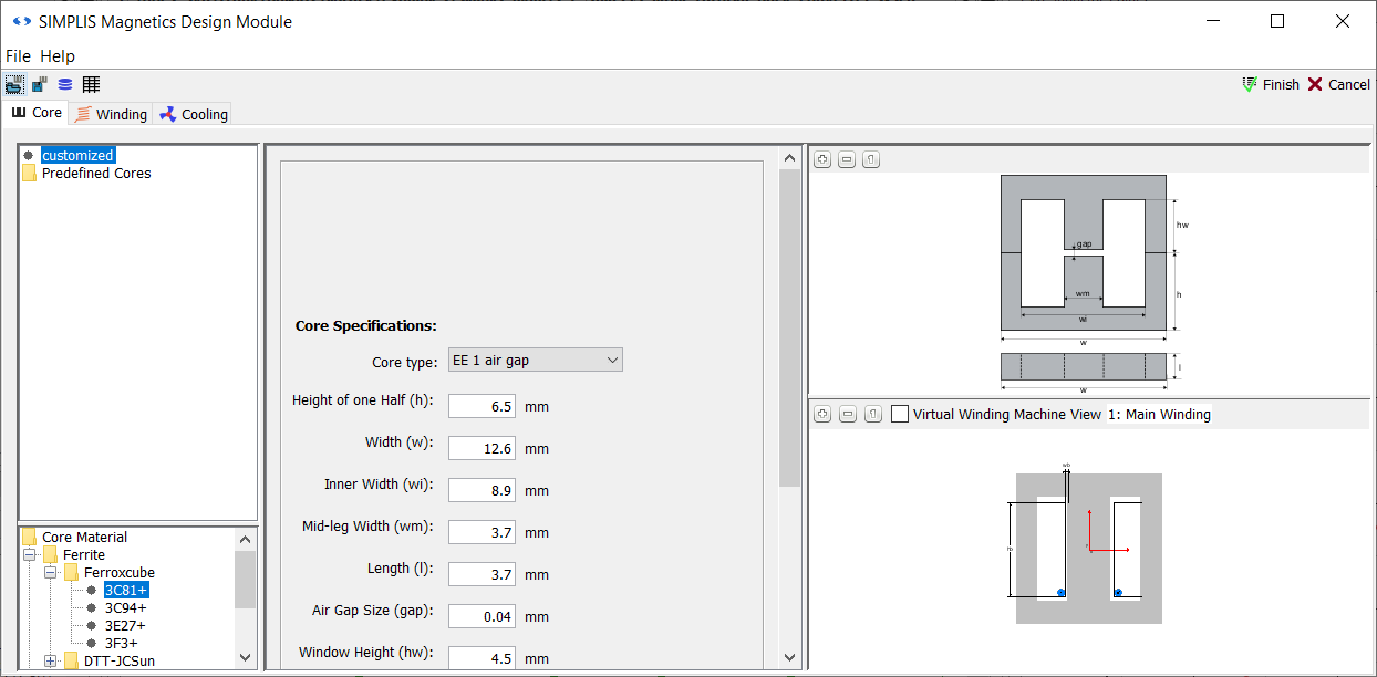
You will notice that while the SIMPLIS MDM main window is open, interaction with the main SIMetrix/SIMPLIS window is blocked. You cannot do anything in the SIMetrix/SIMPLIS Main Window while the MDM main window is open.
By default, a customized EE 1 air gap core is selected, meaning that you must specify all of the core dimensions yourself. However, a large selection of standard core geometries for different shapes is available. To select a pre-defined core geometry:
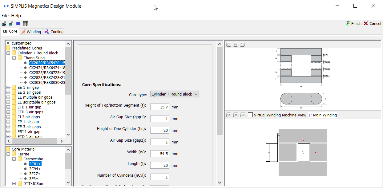
- In the top left selection menu tree, click on Predefined Cores.
- When the menu expands, select the first option: Cylinder + Round Block, and then subsequently select Chang Sung.
- Select the first core in the list, CK2020RBK5420-15.
Result: The "Core" tab should now appear as below:
2.2.2 MagDB
In the top left corner of the MDM main window's Core tab that is selected by default, you will see a selection menu tree with predefined magnetic core shapes and geometries. Since no Level 2 model exists for L1, the first core in the list is selected by default. Below this selection menu tree, in the lower left corner, is another selection menu tree for magnetic core materials. The first material in the core materials list is also selected.
These core geometries and materials, as well as wire geometries and materials, are
defined and stored in MDM's parts database, called MagDB. MagDB can be viewed
in a separate window. To open it, go to File > Open database in the menu bar
of the MDM main window, or click the ![]() button on the main window's
toolbar, right below the menu bar. Once you do this, the MagDB window will open:
button on the main window's
toolbar, right below the menu bar. Once you do this, the MagDB window will open:
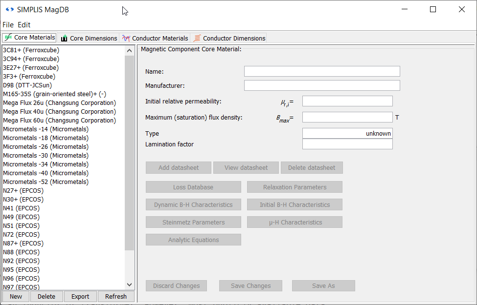
MagDB is opened by default to the first tab, Core Materials, where you can see a list of magnetic core materials available for making a model of a magnetic component using SIMPLIS MDM. The fields to the right are blank since no material is selected in the list to the left. Click on a material in the list to populate the fields with information about that material.
It is important to point out that some materials have a "+" next to their name, for example N87+. MagDB stores information about the losses in the magnetic material at different flux densities, frequencies, temperatures, and DC pre-magnetizations. This information is used to calculate the core losses inside an inductor or transformer. However, most publicly available data sheets only state losses for sinusoidal excitation without any DC pre-magnetization, whereas in many power electronic circuits - such the Buck converter you are using in this tutorial - magnetic components experience piecewise-linear (e.g. triangular) waveforms with a significant DC pre-magnetization or DC bias (e.g. due to the DC current in the inductor). The materials with a + next to their name in MagDB contain loss measurements with triangular flux excitation and a DC bias, taken specifically for SIMPLIS MDM. These measurements allow more accurate core loss predictions than would be possible using standard loss data taken under sinusoidal excitation with no DC bias. In a circuit like a Buck converter, using a magnetic material marked with a + will produce more accurate core loss calculations in MDM than using a material not so marked. Materials not marked with a + contain loss measurements from publicly available data sheets.
You can modify or delete any of the magnetic material information inside MagDB. Deletion is not recommended. Modification should be undertaken very carefully. Instead of modifying an existing entry, it is best to save a modification as a new entry. To do so, follow these steps:
- Select the material 3F3+ (Ferroxcube) in the list to the left.
- In the Name field to the right, change the name to 3F3_2+.
- Change the Initial relative permeability to 2200.0.
- Change the Maximum (saturation) flux density to 0.35.
- Click the Save As button in the lower right corner of the window.
A new material entry, 3F3_2+ (Ferroxcube), appears below the original one in the list. This new entry can now be selected, and the other information about the material (loss measurements, B-H curves, etc.) can be edited. This tutorial will not cover the magnetic material definition is depth. Therefore, delete the new entry you just created by:
- Selecting the material 3F3_2+ (Ferroxcube) in the list to the left.
- Clicking the Delete button, second from the left below the list.
- Clicking Yes in the resulting confirmation dialog which pops up. Result: The material "3F3_2+ (Ferroxcube)" is no longer listed. It has been deleted permanently from MagDB.
Click on the Core Dimensions tab of the MagDB window. In the top left corner there is a list of core shapes. These are the core shapes which are available for magnetic component models in MDM. You cannot edit, delete, or modify core shapes. New core shapes will be added as MDM is updated. However, you can edit the geometries available for each shape, which are listed in the bottom left list. To see all the available geometries for the EE 1 air gap shape:
- Click EE 1 air gap in the top list of core shapes. Result: The top panel displays parameters and a diagram for this core shape. The bottom list now shows only core geometries of this shape.
- Click E20-0.50mm in the bottom list of core geometries. Result: The bottom panel displays parameters and a diagram for this core geometry:
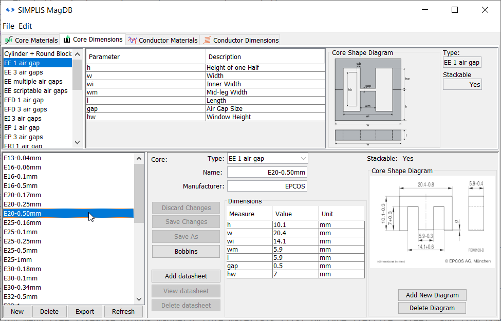
The core geometry can now be edited in a similar fashion to the core material. A similar procedure can be followed in the Conductor Materials and Conductor Dimensions tabs. Feel free to browse MagDB. Once you are done, close the MagDB window by selecting File > Exit/Close from the MagDB window menu bar. Now you will return to the main MDM window and look at its tabs one by one.
2.2.3 MDM Main Window Core Tab
The core geometries in the selection menu tree are grouped by core shape and manufacturer. For most core shapes, there is a 1 air gap and a 3 air gaps variant. The 1 air gap cores have a pre-manufactured, predefined air gap which cannot be modified, typically on the middle leg of a three-legged core. The 3 air gaps cores typically consist of two identical core halves, where a custom air gap can be defined by placing a spacer in between the two core halves. For two-legged cores, such as U-U cores, there are 2 air gaps as well as multiple air gaps variants. In the latter, an arbitrary number of air gaps can be specified.
You are not limited to the cores that are already saved in MagDB. For any design, you can enter a custom, unique core geometry by selecting customized at the top of the core geometry selection menu tree. Then in the middle panel, you can select the core shape from the Core type: drop-down menu, and then enter the value for each core dimension below.
The bottom left selection menu tree likewise groups magnetic core materials first by type (ferrite, steel, and iron powder) and then by manufacturer. You can only select a core material from the menu. Unlike with the core geometry, you cannot define a custom core material in the Core tab of the main MDM window. If you wish to use a material which is not listed, you must first add it to MagDB as described in the previous section.
The upper right corner of the Core tab shows the diagram of the selected core shape. This
image is static and does not change as you design your magnetic device. It defines each dimension of the core shape which needs to completely define a core geometry. Above the diagram are three buttons. You can zoom in the diagram by
pressing the![]() button (first from the left) and
zoom-out by pressing
button (first from the left) and
zoom-out by pressing![]() button (second from the left). The
view can be reset to show the entire diagram by pressing the
button (second from the left). The
view can be reset to show the entire diagram by pressing the![]() button (third from the left).
button (third from the left).
The lower right corner of the Core tab shows a visualization of the magnetic device being designed, in this case an inductor. Shown is a cross-section of the core with any windings that are placed. The same zoom controls exist as for the upper diagram. You can also zoom in and out using the middle scroll wheel of your mouse. Click and hold on the drawing and drag to move it. If you zoom in enough, you will see a single turn of wire placed by default visible around the left leg of the core, at the bottom of the core winding window. This is because the core selected by default as first in the list is very large compared to the wire selected by default.
You can resize the main MDM window to a size of your choosing, and you an also resize the panels of each tab relative to each other. If the window appears too small at your screen resolution, feel free to resize and rearrange it to your liking.
2.2.4 MDM Status Window
As you build up the design of your component, you can get more information to help
you along by opening the SIMPLIS MDM Status Window. To show it, select
File > Show status window from the main MDM window menu bar, or click
the![]() button on the toolbar below the
menu bar. The MDM Status Window will open:
button on the toolbar below the
menu bar. The MDM Status Window will open:

As you interact with the main MDM design window, status and error messages are printed to the MDM Status Window. There are two pieces of information which are the most useful to you at this point. The first is the lineage showing the current model status. If it displays "Model status: OK!" as above, then the currently defined model is a physically valid inductor design. Important note: this does NOT necessarily mean that your inductor satisfies your design requirements. That is up to you to determine. It only signifies that the inductor model as currently defined is something that can, as far as MDM knows, be built. If the model status is not "OK!", an error message will be displayed, for example notifying you that the currently specified number of turns of the currently selected wire cannot fit in the winding window of the currently selected core.
The second piece of information is the initial inductance of the inductor as currently defined. In this case, you should see a line which says "UU-cyl-Inductor: L = 0.2592 µH (based on initial permeability)".
The MDM Status Window can be closed at any time and opened at any time when the MDM main window is active. Keeping the Status Window open does not block SIMetrix/SIMPLIS like the main window does. It can be minimized or placed in the background and you can continue with your work. Closing it does not erase any of the messages printed to it, so you can always go back and examine every message printed since the beginning of the current MDM session.
Now move the Status Window to the side so you can see the entire MDM main window again.
2.2.5 MDM Main Window Winding Tab
Go back to the MDM main window and switch to its Winding tab. Here you define the winding of the inductor: the wire to use, the number of turns of the wire, and how the turns are arranged in the winding window.
In the upper left corner is a spinner that changes the number of turns. You can increment or decrement the number of turns by one by clicking the spinner arrows, or enter a number of turns directly. To the right is a visualization of the inductor, as in the Core tab, but larger. Increment the number of turns one by one until you reach 10 turns. With each increment, you should see a new turn being drawn on the visualization to the right, and the status window should display at each increment the new initial inductance of the inductor. Therefore, as you are designing your component, you can see at each step its physical representation and its inductance.
Defining the Winding Bobbin
Below the spinner for the number of turns is a panel which defines the winding. It is divided into three sub-panels. The first is the Bobbin sub-panel. Here you define the bobbin (coil former) into which the core is placed and around which the winding is wound. You need to define two parameters:
- The Bobbin Gap (wb) which is the distance between the core leg and the outer side of the bobbin on which the winding is placed. It represents both the thickness of the bobbin itself and the gap (if any) between the bobbin and the core.
- The Bobbin Height (hb) which is height (or length) of the bobbin along which the turns can be wound.
These two bobbin dimensions are shown on the visualization to the right of the Bobbin sub panel.
There are two ways in which a bobbin can be defined, and they can be selected from drop-down menu next to Bobbin Parameters. For a quick initial design, Relative Bobbin can be selected. In this case, the bobbin dimensions are defined dynamically as a proportion (from 0 to 1) of the core winding window. For a real-world detailed design, Absolute Bobbin should be selected and the bobbin dimensions entered in millimeters. To change the bobbin:
- Switch the drop-down menu next to Bobbin Parameters to Absolute Bobbin.
- Change the Bobbin Height (hb): to 17. Result: The "hb" dimension on the visualization to the left should become smaller.
Defining the Winding Pattern
Below the Bobbin sub-panel is the Winding Pattern sub-panel. Skip it for now. Scroll down to the last, unnamed sub-panel below it. This is where you will define the wire dimensions for the design.
Defining the Wire Dimensions
To the left, similar to the Core tab, is a list of wire geometries. The wire geometries are alphabetically listed, and not grouped by type. You can find the type (shape) of each by clicking on it. Like with the core geometries, you can define a custom wire geometry by selecting customized at the top of the selection menu tree.
The wire material can only be selected from existing entries in MagDB. Like with the core materials, if you wish to define your own wire (conductor) materials, you must add them to MagDB first. The default material is Copper (drawn wire). This can be changed in the drop-down menu at the top of the sub-panel.
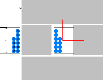
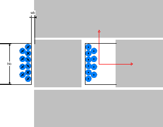
In the following procedure, the bobbin Height has been changed to 17mm and the
number of turns is 10. The winding view is as follows: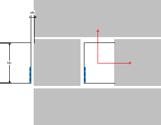 .
.
To change the wire and the winding:
- Scroll the selection menu tree to the top. Select the wire AWG10.
Result: The turns visualized to the right should become noticeably larger:
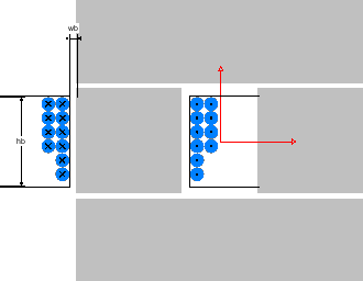
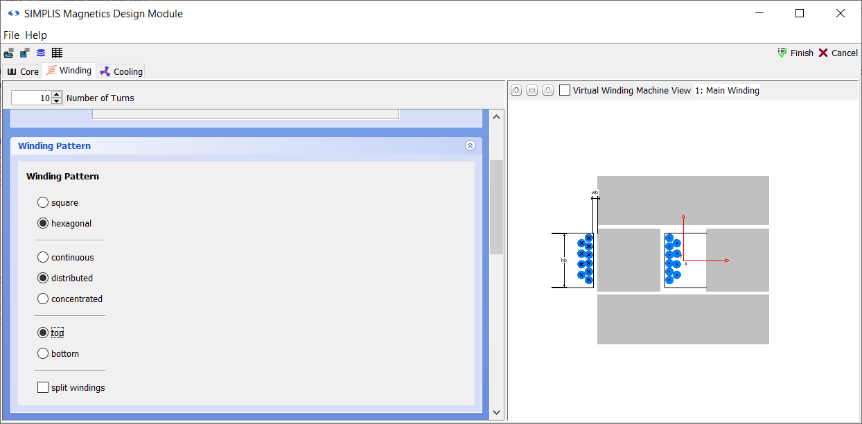
- Scroll back up to the Winding Pattern sub-panel. Here you can change
how the turns are distributed around the bobbin. First, in the lower-most
section, click the top radio button.Result: The turns are now placed from the top of the core, rather than from the bottom as before:
- In the upper-most section, click the hexagonal radio button. Result: The turns of the second layer of the winding are now placed in between the turns of the first layer:
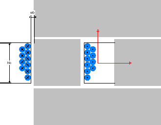
- In the middle section, click the distributed radio button. Result: The turns are now distributed along the bobbin:
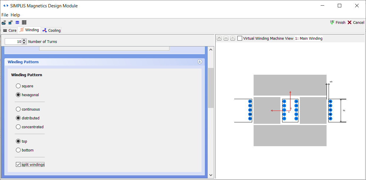
- Since this is a two-legged core, you can split the winding across the two
legs. Check the split windings box at the bottom of the Winding
Pattern sub-panel. Result: The winding is now wound around both legs of the core:
2.2.6 MDM Main Window Cooling Tab
Now switch to the Cooling tab in the MDM main window. Here you define the thermal and cooling properties of the design.
First, you can select the Cooling Concept from the drop-down menu in the left top corner. The default is Natural Convection which models the cooling of the inductor assuming there are no heat sinks or active cooling system (e.g. a fan) of any kind, but that all sides of the inductor are open to the air into which heat can escape.
To model the existence of a heat sink on which the inductor may be placed, or the fact that some sides of the inductor are placed on a material which will not conduct heat, you can change the check boxes under Convection Sides. The small diagram to the right indicates how the sides of the inductor are named. By default, all are checked, meaning that all sides conduct heat by natural convection. To change this,
- Uncheck the box front. Result: A box appears next to "front" indicating a thermal resistance of infinity.
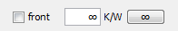
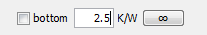
- Leave the thermal resistance of the front side as-is, meaning that it will not conduct any heat. Uncheck the box bottom.
- In the box which shows up next to "bottom", enter a thermal resistance of
2.5. Result: This models the attachment of this side of the inductor to a heat sink or other thermally conductive element with a thermal resistance of 2.5K/W.
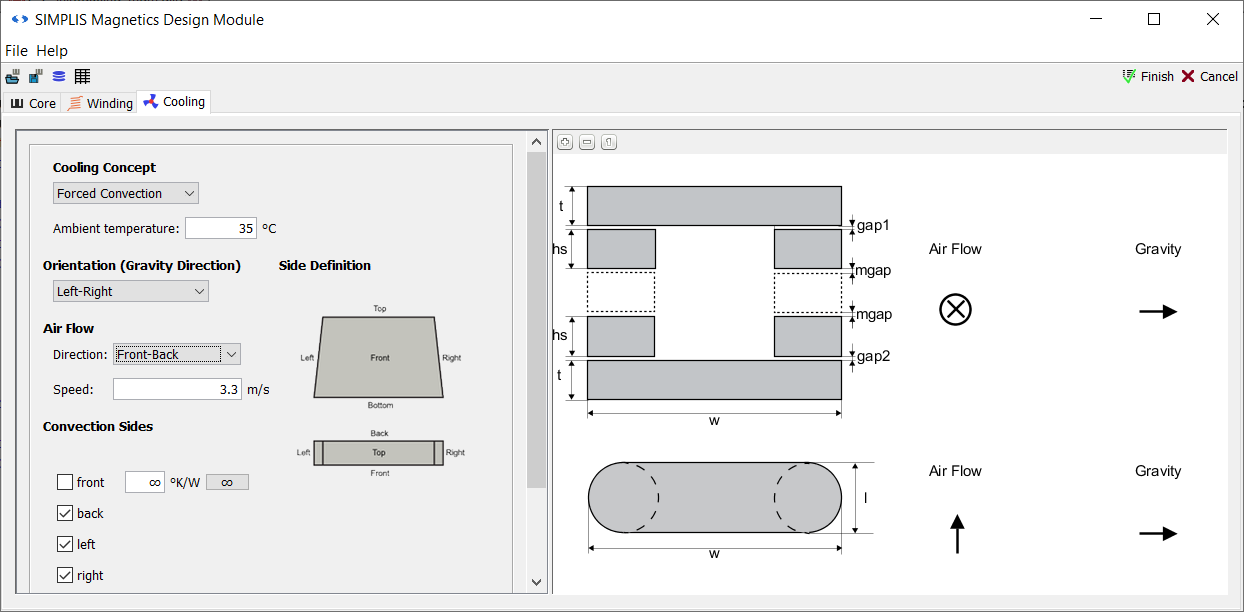
Now change the convection type. To model the existence of a fan, change the Cooling Concept to Forced Convection. The thermal resistances of the different sides that you defined previously are preserved. The sides which are still checked are now all exposed to forced air flow. Now, the following elements can be set:
- The Ambient temperature defines the temperature at which the inductor is before any current or voltage is applied to it. It cannot fall below this temperature. Change it to 35.
- The Orientation (Gravity Direction) defines how the inductor is oriented
compared to the direction of gravity. In the right panel of the tab you can see
a diagram of the core from the front and the top, and beside that the air flow
and gravity direction relative to the core. The Orientation is set for both
natural and forced convection. Change the Orientation to
Left-Right in the drop-down menu. Result: The arrows indicating gravity change on the diagram to the right.
- For forced convection, you must also specify the air flow direction. In the
Direction drop-down menu, select Front-Back. Result: The arrows indicating air flow change on the diagram to the right.
- Finally, the air speed of the forced air flow must be specified. Change the
Speed to 3.3
Result: You should now see the following:
Focus returns to the main SIMetrix/SIMPLIS window which is now unblocked. Since you clicked Cancel, you have not saved your inductor model and a Level 2 model for L1 does not exist yet. You will create one in the next section: 2.3 Design an Inductor Using MDM