Overview
- Prototyping new digital control algorithms
- Creation of models with large amounts of digital content without having to implement with SIMPLIS primitives
- Distribution of models to customers/end users without having expose Verilog-HDL source
Licensing
The SIMPLIS Digital DLL feature will be enabled for all in-maintenance users of SIMetrix/SIMPLIS Pro and Elite v8.40 and above at no additional charge. Users of the standard SIMetrix/SIMPLIS product will need to upgrade to Pro or Elite in order to run simulations containing digital devices modeled by a C/C++ DLL.
Technical and Usage Highlights
To get up and running with a new DLL-defined digital device, the program ships with some built-in convenience utilities. Two prominent examples include automatic symbol and edit dialog creation, as well as a project creation function that outputs a source code outline of your device and a ready-to-build Visual Studio® project file.
Like the SIMPLIS VH module, and in contrast to the SIMPLIS primitive components, DLL-defined digital devices support bus-oriented I/O with built-in support for Unsigned, Two's Complement and Binary Offset encodings. Functions are made available so that during simulation, bus values can be read from and written to as integers instead of individual bits. The default autogenerated symbols allow for bus wiring and probing.
DLL-defined digital devices fully support parameterization as well as Monte Carlo and Multi-Step analysis types using the multi-core functionality.
Requirements
- SIMetrix/SIMPLIS Pro or Elite v8.40 or later
- The SIMPLIS Digital Development Kit (providing header files and the tutorial examples)
- a C/C++ Compiler Toolchain (e.g. Visual Studio®)
- If Visual Studio® is used, the "Desktop development with C++" Workload is required.
Cautions and Caveats
DLL-defined Digital Devices run inside the SIMPLIS Advanced Digital simulation engine and so share the same advantages and limitations. A few things to note.
Like all other devices running in the Advanced Digital simulator, a non-zero output delay is enforced. This eliminates problems associated with the classic SIMPLIS logic gate's ability to instantaneously switch state with zero delay.
While ultimately dependent on the specific circuit and operating conditions, for digitally controlled systems where the signals in the feedback loop are quantized into discrete levels, the POP / AC analysis is typically not applicable. The extremely small perturbation of the injected signal during the AC analysis is not large enough to produce a control loop response. These circuits are usually better suited to the SIMPLIS Multi-Tone AC Analysis.
Using a DLL-defined Device in your Design
To instantiate a DLL-defined device on the schematic, use the menu item .
Choose the appropriate DLL file with the file selection dialog and click "Open". DLLs that contain only one device definition will automatically select that device and instantiate a symbol for you to place on the schematic.
DLLs that contain multiple device definitions will present the user with a list dialog
allowing them to select the device they wish to place. 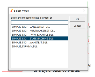 Select the appropriate option from the list and choose "OK". The system will
automatically create a symbol that can be placed on the schematic.
Select the appropriate option from the list and choose "OK". The system will
automatically create a symbol that can be placed on the schematic.
Creating a DLL-defined Digital Device
- the device name and version number
- input and output bus names and widths
- parameter names, types (integer, unsigned integer, double) and default values
- a function to initialize the device (called setup)
- a function to set the initial condition of the output at t=0 (called set_initial_condition)
- a function to set the output during simulation (called action)
An Overview of the Simulation Life-Cycle
- Syntax Checking
- Setup
- Setting of Initial Conditions
- Action During Simulation
- Teardown When the Simulation Completes
Syntax Checking
- the referenced DLL file can be found and loaded
- a device specification is returned from the call to get_device_spec
- the device when instantiated meets the high-level requirements (e.g. no more than 64 input or output buses, at least one output bus or pin, etc...)
- the device parameter types match the specification
Setup
Every time that SIMPLIS loads a DLL-defined Digital Device, the setup routine is called, providing the opportunity to perform housekeeping and initialization activities. This function is called only once at the beginning of the SIMPLIS run. The logic and state of the input buses/pins of the device are not known at this time, only the user's input from the edit dialogs should be relied upon.
- get parameter values that the user has provided via the edit dialog
- ensure that the users' passed in parameter values are logical and consistent
- instantiate managed and unmanaged user storage, if required
- get pointers to any frequently accessed buses/pins, if desired
- perform any required initial or one-time calculations
Initial Conditions
Part of the device specification is to provide a function that sets the initial conditions (value at t=0) of the device's output based on the parameters that the user has passed via the netlist (called set_initial_condition).
This function is called only once (after the call to the setup function) at the beginning of the SIMPLIS run if the simulation starts at t=0.
As with the setup function, the logic and state of the input buses/pins of the device are not known at this time, only the user's input from the edit dialogs should be relied upon.
- perform any required initial calculations
- assign the values of the output buses/pins at t=0 based on user input
- schedule any necessary wake requests relative to t=0
Action
- one or more of the device's input buses/pins change
- a wake request occurs having been previously scheduled by a call to the set_scheduled_wake function during either the set_initial_condition or action function
- the current simulation time
- the struct containing pointers to the functions the DLL can call
- the struct detailing the reason the device was awoken
- read the values from a bus or pin
- detect pin edge events (positive, negative or both)
- execute necessary calculations
- assign values to output buses/pins
Teardown
After the simulation is complete, SIMPLIS will give each device instance the opportunity to clean up after itself, freeing any allocated memory, closing any opened files, etc...
The teardown function will be called only once at the end of the simulation, immediately before the program exits.
After the teardown function is called, SIMPLIS will call FreeLibrary, decrementing the reference count for that DLL.After the teardown function is called, SIMPLIS will call FreeLibrary, decrementing the reference count for that DLL.
During the device's teardown function, it should not attempt to read from or write to any buses or pins, nor should any events be scheduled.
User Data Storage
Because of the need to support analysis types that are multi-core enabled (Monte Carlo and Multi-Step), as well as to give proper results in situations where SIMPLIS rejects timesteps and will appear to "turn back time", the use of global variables in the DLL scope is highly discouraged. Two types of user data storage are provided for in the DLL-defined Digital Device specification, managed and unmanaged.
Managed User Storage
To store volatile information that is not "output" (internal variables, previous states or samples, etc...), a DLL-defined device can allocate a chunk of memory that will be managed by SIMPLIS so that it is always presented with the "correct" values that were assigned during the prior device wake event. This incurs some computational overhead for every wake event and so should only be utilized when necessary.
If at t=n, the action function is invoked for a device with managed user data storage,
the following diagram describes how it is handled and presented in the DLL.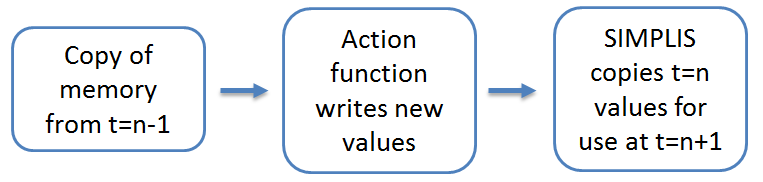
If SIMPLIS later rejects a timestep and rolls back to t=n, the correct values from t=n-1 will be presented again correctly.
Since copies are being kept and managed until the timestep is accepted, additional CPU and Memory resources are used.
Unmanaged User Storage
- parameter values passed via the edit dialog
- pointers to buses and pins
- intermediate variables derived from parameters that do not change during simulation
Packaging a Device Definition into a DLL
- p_smx_dll_device_spec* smx_dll_get_supported_devices( void )
Returning a NULL-terminated array of pointers to device specifications made available by that DLL.
- p_smx_dll_device_spec smx_dll_get_device_spec(char* name, SMX_DLL_UINT32
version)
Returning the device specification that matches the name and version number requested by the schematic symbol.
The code template generation function creates a working version of both of these functions by default.