2.1 Buck Converter Circuit and Inductor
This section of the tutorial introduces the Buck converter circuit that will be used, goes over the basics of the Multi-Level Lossy PWL Inductor (Version 8.0+) in SIMPLIS and introduces the new Level 2 inductor model.
In this topic:
Key Concepts
This topic addresses the following key concepts:
- The new magnetics models introduced by SIMPLIS MDM are integrated into and are an extension of the multi-level modeling paradigm of SIMPLIS.
- To use MDM to design inductors, the new Level 2 model of the Multi-Level Lossy PWL Inductor (Version 8.0+) must be used.
- Inside a SIMPLIS schematic, the inductance of the Multi-Level Lossy PWL Inductor (Version 8.0+) is specified by a piecewise-linear current-flux linkage curve.
What You Will Learn
In this topic, you will learn the following:
- Review the model levels of the Multi-Level Lossy PWL Inductor.
- How to identify if SIMPLIS MDM is available on your system by looking for the Level 2 model in the Edit Multi-Level PWL Inductor dialog.
- How the Level 2 model differs from a Level 1 model.
2.1.1 Open the Schematic
Open the schematic 2.1_SIMPLIS_MDM_tutorial_buck_converter.sxsch from the directory of example schematics you previously downloaded. You should see the following:
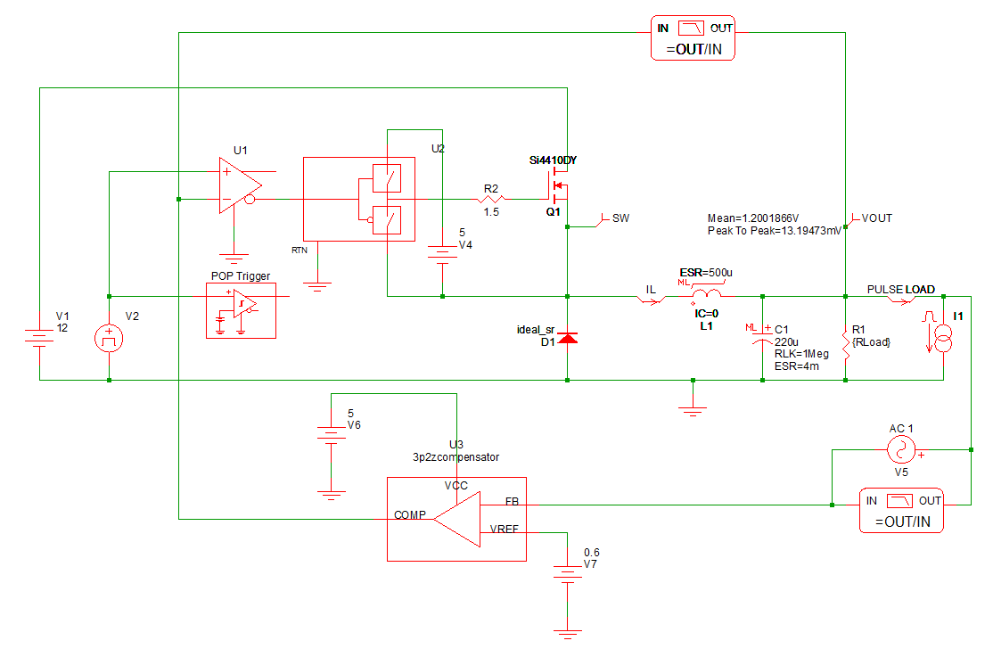
Feel free to examine the circuit by double-clicking on the various symbols. The input voltage is set by V1 to 12V. The output voltage of this buck converter is regulated by a 3-pole, 2-zero voltage mode compensator. The DC output load current is currently set to 5A, with a maximum design load of 10A. In this tutorial, you will modify the inductor design only; therefore, do not change any parameter values in the circuit, except as instructed in this tutorial.
This example schematic is set up for a steady-state analysis using the SIMPLIS Periodic Operating Point (POP) Analysis. The POP analysis finds the steady-state operating point of the circuit and displays an integer number of steady-state switching periods in the Waveform Viewer. To review the types of the various SIMPLIS simulations, please refer to section 3.0 Simulating the Design of the SIMPLIS Tutorial.
2.1.2 Examine the Inductor Model
Symbol L1 in this Buck converter schematic is the output energy-storage inductor which you will be designing in this tutorial. As mentioned earlier, it is a Multi-Level Lossy PWL Inductor (Version 8.0+). To review the concept of multi-level models as used in SIMPLIS, please refer to section 2.3 Edit Multi-Level Models of the SIMPLIS Tutorial.
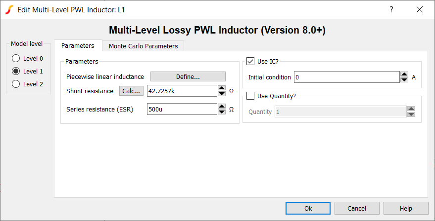
You will see that this inductor has a Level 1 model specified for it. Prior to the release of SIMPLIS MDM, this inductor part only had two model levels: 0 and 1. To review:
- A Level 0 model consists of a piecewise-linear (PWL) inductance defined by a flux linkage vs. current curve with a shunt resistance. No series resistive loss is modeled.
- A Level 1 model consists of a PWL inductance defined by a flux linkage vs. current curve, a shunt resistance, and an equivalent series resistance (ESR) to model low frequency conduction losses.
You can examine and modify the PWL curve that defines the inductance by clicking the Define... button in the above dialog.
SIMPLIS MDM introduces the Level 2 model. If you do not have a valid license for SIMPLIS MDM, you will not be able to see the "Level 2" radio button in the above dialog. If you are able to change to the Level 2 inductor model, then you are using a version of SIMetrix/SIMPLIS which supports MDM and you have a valid MDM license. If you are reading this tutorial and would like to evaluate MDM, please send an evaluation request to: sales@simplis.com.
2.1.3 Level 2 Inductor Model
Click on the Level 2 radio button in the Edit Multi-Level PWL Inductor dialog. You should see the following:
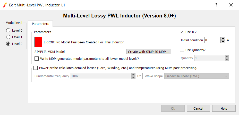
The model status box is red and the message "ERROR: No Model Has Been Created For This Inductor" is shown. This is because this inductor does not currently have a SIMPLIS MDM model. Until you create a model with SIMPLIS MDM, you cannot click OK in the dialog while the level is set to 2.
In terms of what is used in the simulation of the schematic, the Level 2 model is identical to the Level 1 model in structure; it contains a PWL inductance, a shunt resistance, and an ESR. However, unlike with the Level 1, these parameters cannot be entered or edited by the user directly. They are extracted from the physical model of the inductor which the user builds using MDM.
Note the checkbox labeled "Write MDM generated model parameters to all lower model levels?". When you create a level 2 model and this box is checked, the PWL inductance and shunt resistance calculated by MDM will automatically be written into the Level 0 and Level 1 models, and the ESR calculated by MDM will be automatically written into the Level 1 model, associated with this symbol. Consequently, any user-defined parameters for the Level 0 and 1 models would thus be overwritten. Checking this option makes the different model levels consistent with one another, and ensures that changing keeps the different model levels consistent with the physical model that you design in MDM. If you were to switch from a Level 2 to a Level 0 model, the Level 0 model would not include ESR losses when you simulate the schematic, but the PWL inductance would remain the same.
Click Cancel to close the dialog, discarding any modifications you may have made.
2.1.4 Run the Simulation
Run the simulation (press F9, click the appropriate button on the toolbar, or from the menu bar select Simulator > Run Schematic). The Waveform Viewer should appear, and you should see, from the top, three steady-state switching cycles of the output voltage, inductor current, and switching node waveforms:
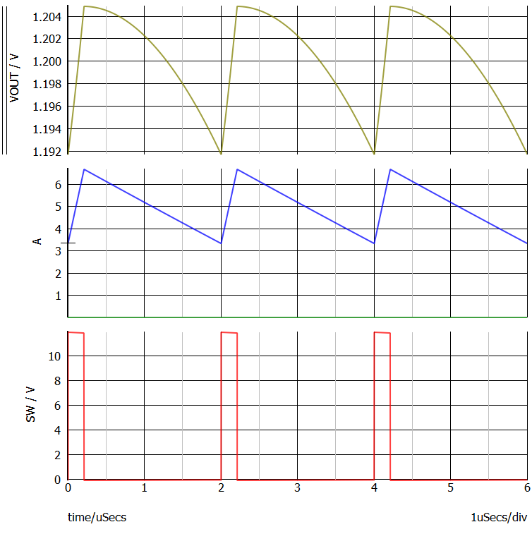
Note that the maximum inductor current is less than 7A.
Since you are using a PWL inductor in this schematic, a single inductance value is not displayed anywhere. To see the PWL inductance curve,
- Right-click the symbol L1
- In the resulting menu, select Plot PWL points for R, L, TX, or C.
Result: A new tab, PWL Inductor Points will appear in the Waveform Viewer:
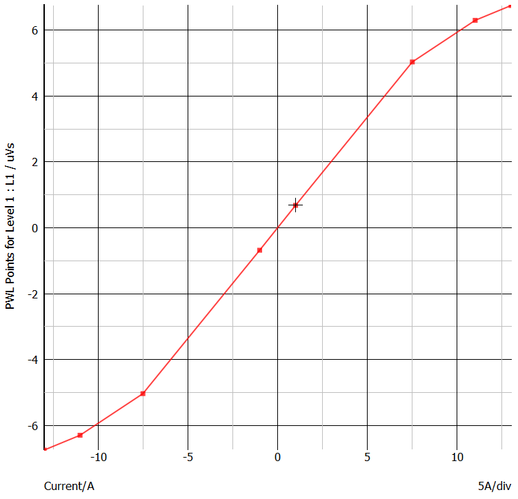
You can see that the flux linkage vs. current characteristic is constant when iL is in the range of -7.5A to 7.5A. As we noted above, the peak inductor current is less than 7A. This means that the converter is operating in the linear range of the inductor L1. In other words, the inductor does not enter saturation under these operating conditions. The differential inductance is the slope of the flux linkage vs. current curve. You can calculate the inductance from the flux linkage vs. current characteristic in the following manner. We can see that, when the inductor current is 7.5A, the flux linkages equal approximates 5 uVolt-seconds. The slope of the linear portion of the flux linkage vs. current characteristic of this inductor is 5uVs/7.5A = 667nH.
Therefore, for this circuit, you will use SIMPLIS MDM to design an inductor with an inductance of approximately 600 to 700 nH. The goal is to replace the existing Level 1 model with a Level 2 model with approximately the same performance in the electrical schematic as the Level 1 simulation model.