2.4 Refine the Inductor Design Using MDM
In this section you will improve the inductor design you created in section 2.3 Design an Inductor Using MDM in order to reduce its size (boxed volume) and proximity losses.
In this topic:
What You Will Learn
In this topic, you will learn the following:
- How to modify an existing inductor design in MDM and analyze the results.
- How to create a customized wire geometry.
2.4.1 Change the Inductor Design
As noted in Analyze Results Section, the design you created previously uses a core which is too large. The analysis of the results suggest that the core can be much smaller. Therefore the first step is to select a smaller core, and then redesign the winding to achieve the desired inductance:
- Double click the L1 symbol.
- In the resulting dialog, click on the Edit with SIMPLIS MDM... button.Note: If you have left the MDM Results window open, the main MDM window may now flash minimized in the task bar instead of showing immediately in the foreground. If this is the case, simply click on the SIMPLIS icon on the taskbar to bring the MDM window up.
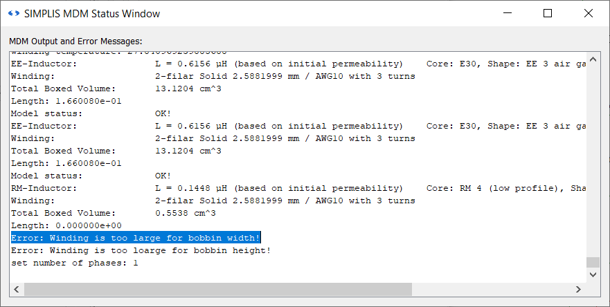
- Open the MDM Status Window and move it to the side.
- Select a much smaller core. Go the Core tab. One of the smallest cores available in the MDM database is an RM4 core. In the core geometry selection tree menu, scroll down and
select RM 3 air gaps > EPCOS > RM 4 (low profile).
Result: The winding is too large to fit into this core. The Status Window will displays an error message: Error: Winding is too large for bobbin width!
- Click 1 to re-center the inductor visualization. You can see that the air gap far too large for this core.
- In the middle panel of the Core tab, scroll down and set the Air Gap Size (gap) to 0.05 and press Enter.
- Go to the Winding tab. Scroll down to the wire selection tree menu, and select Predefined Windings > AWG21.
Result: The wire is small enough to fit into the core winding window with three turns of bifilar wire:
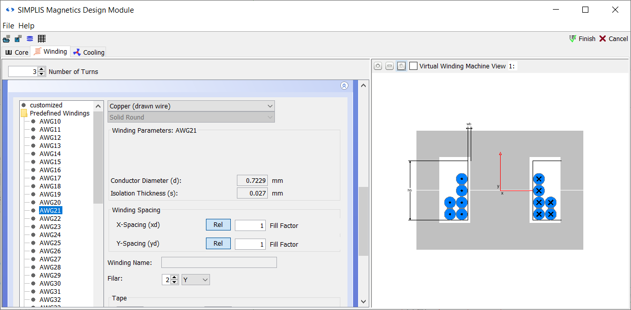
- Take a look at the MDM Status Window. You will see now however that the inductance of the inductor is 1.8341uH. This is too large.
- Therefore reduce the number of turns in the Winding tab to 2. Now the inductance is 815.2nH.
- Go back to the Core tab, and increase the Air Gap Size slightly to 0.07.
- Return to the Winding tab. In the MDM Status Window, the inductance is updated and shown to be 611.3nH. You know have the desired inductance with the new core.
You know have an inductor with a smaller core and air gap. However with the selected wire, you can see that there is still a lot of free space in the core winding window. Fill that space more tightly with copper:
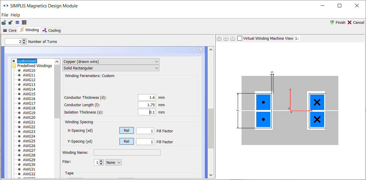
- In the wire geometry selection menu tree, select customized.
- Change the Filar spinner to 1, and in the drop-down menu next to it select None.
- In the second drop-down menu at the top of this sub-panel, change the selection from Solid Round to Solid Rectangular.
- In the Winding Parameters section, set the Conductor thickness (d): to 1.6.
- Set the Conductor Length (l): to 1.75.
- Set the Isolation Thickness (s): to 0.1 and press Enter.
Result: You have now created a customized winding made of square wire that almost entirely fills the winding window:
- Click Finish.
- Close the MDM Status Window.
Save this schematic as 2_my_buck_RM4_core.sxsch.
A complete schematic with the inductor design developed in this section, set up for MDM post-processing, is available as 2.4_SIMPLIS_MDM_tutorial_buck_converter_RM4core.sxsch in the zip archive of schematic files.
2.4.2 Run the Simulation and MDM Post-Processing
Press F9 to run the simulation. As before, after the circuit simulation is completed, MDM post-processing will run, and when finished, the MDM Results window will be displayed:
You may have noticed that the post-processing took longer this time. This is because it takes longer to calculate losses for rectangular and foil windings in MDM than it does for windings made from round wires.
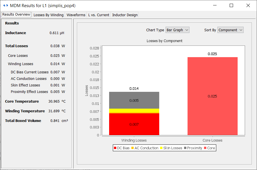
2.4.3 Analyze the New Results
First take a look at the Total Boxed Volume. It is now only 0.841cm3. This is 15.6 times smaller than the previous design with the E30 core.
You will also see that the DC winding losses are approximately the same as before at 7mW, but that the total winding losses are now much lower. The proximity losses are now much reduced at only 5mW, lower than the DC losses. You can confirm this by also looking at the Losses By Winding tab:
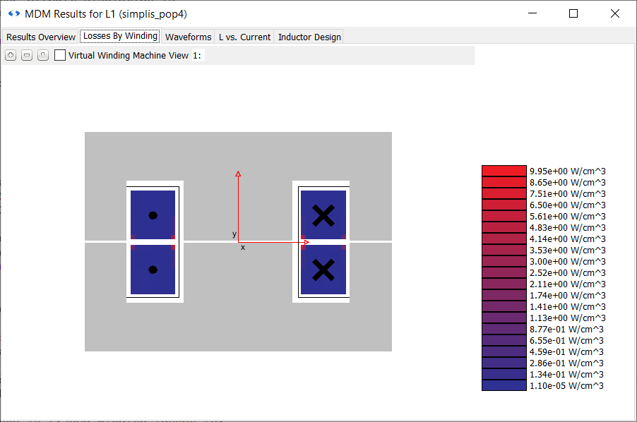
Note that the turns are coloured red only around the edges closest to the air gap. If you
cannot see this, zoom in by pressing the![]() button or
using the middle scroll wheel of your mouse. The visualization in the Results window works
the same way as those in the Core and Winding tabs of the main window.
button or
using the middle scroll wheel of your mouse. The visualization in the Results window works
the same way as those in the Core and Winding tabs of the main window.
However, despite drastically reducing the winding losses - by almost two-thirds - the total losses are actually not so drastically reduced compared to the first design, at 38mW. You can also see that the inductor is now getting significantly hotter - not too hot, but it is now about 7 degrees above ambient.
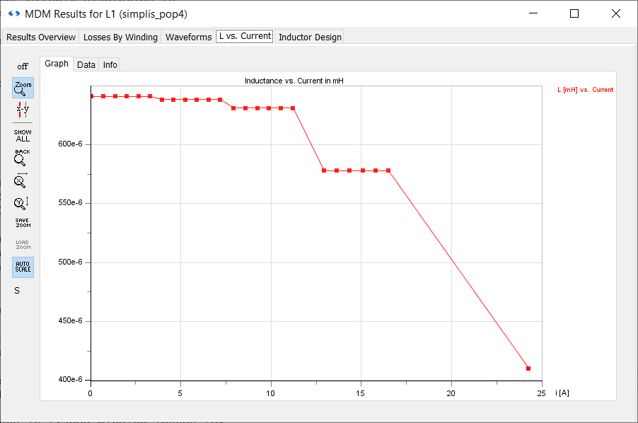
What you have done in this design compared to the first one is traded winding losses for core losses: they are now much larger at 25mW. If you look at the Waveforms tab, you will see reason for this: the peak flux density inside the core is now much larger at 176mT. Going to the L vs. Current tab, you will see that the inductor now saturates around 16A, with the first major inductance drop at 7.2A - close too but still above the peak inductor current:
The final result is an inductor which has an acceptable temperature rise, approximately the same losses and significantly smaller volume than the first design. Therefore, this refined design is a great improvement on the initial design you created in the previous section.