PWL Capacitors
The SIMPLIS Piecewise Linear (PWL) capacitor is used to model a voltage-dependent capacitance, such as a junction capacitance. The PWL capacitor is defined with a series of points on an x-y plane where the charge is on the vertical axis and the voltage is on the horizontal axis. With this definition, the charge is always continuous as the voltage across the capacitor varies.

A common use for the PWL capacitor is to model the non-linear capacitances in semiconductors. The model parameter extraction routines automatically generate the points to define SIMPLIS PWL capacitors.
A good description of the PWL modeling techniques using PWL capacitors can be found in the Piecewise Linear Capacitors section in SIMPLIS is Always Piecewise Linear, All the Time.
In this topic:
Capacitance to Charge Converter
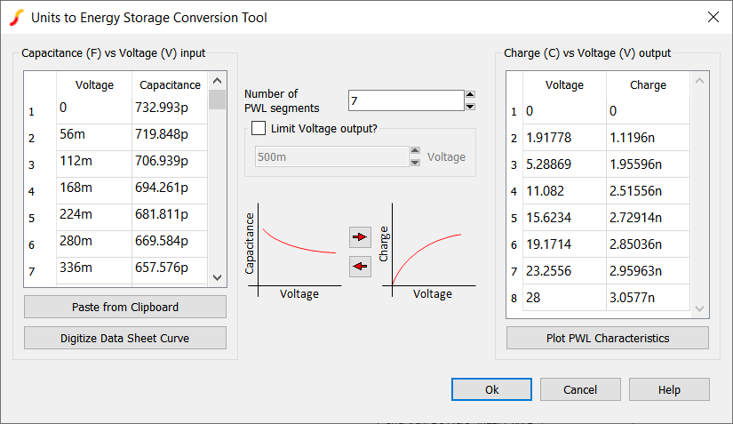
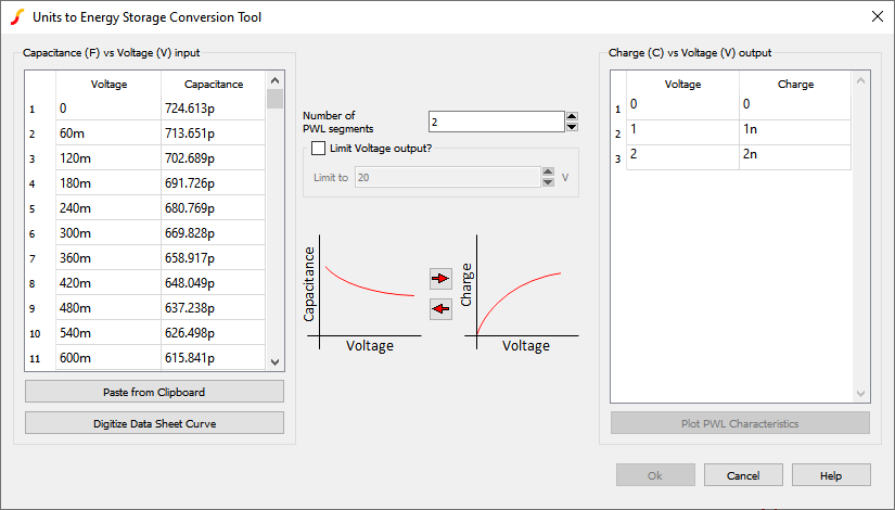
Introduced in version 8.4, a tool has been added that will allow the user to enter the capacitance (in Farads) vs voltage characteristics and convert to a charge (in Couloms) vs voltage PWL capacitor. With Pro and Elite licenses, the Digitise Datasheet Curves tool is encorporated to import the capacitance vs voltage characteristics.
- Place a PWL Capacitor and open it's editing dialog.Result: The Define PWL Capacitor dialog will open.
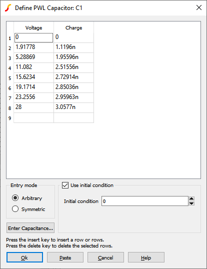
- Press the Enter Capacitance... button.Result: The conversion tool will open.
| Label | Units | Description |
| Capacitance (F) vs Voltage (V) input | F and V | Capacitor characterization defined in Farads vs Voltage |
| Paste from Clipboard | n/a | Will paste tab delimited data from the clipboard to the Capacitance vs Voltage table |
| Digitize Data Sheet Curve | n/a | Will
open the Digitise Data Sheet Curve tool Note: Digitise Data Sheet Curve
tool available for Pro or Elite Licenses
|
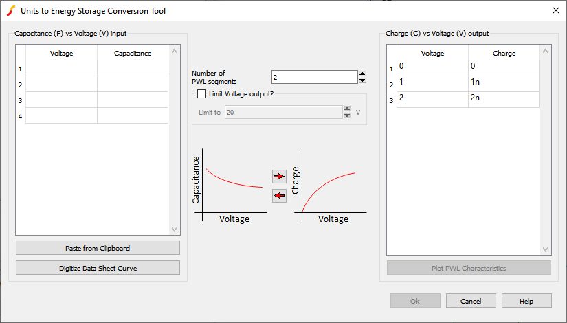
| Number of PWL Segments | n/a | Defines the number of PWL segments for the Charge vs Voltage characterstics |
| Limit Voltage output? | n/a |
|
| Limit to | V | |
| n/a | Will convert your Capacitance vs Voltage characteristics to PWL Charge vs Voltage characteristics | |
| n/a | Will convert your Charge vs Voltage characteristics to Stepwise Linear Capacitance vs Voltage characteristics | |
| Charge (C) vs Voltage (V) output | C and V | Capacitor characterization defined in Charge vs Voltage |
| Plot PWL Characteristics | n/a | Will plot the Capacitance vs Voltage and Charge vs Voltage characteristics |
PWL Capacitor Example
This circuit example was created by using the Capacitance to Charge conversion tool to digitize the example non-linear junction capacitance datasheet curve and convert the results in to a PWL model. The circuit file and example datasheet curve can be downloaded here: simplis_004_pwl_capacitor_example.zip
The procedure is as follows:
- A PWL Capacitor was placed on a schematic.
- The Capacitance to Charge conversion tool was opened.
- The Digitise Datasheet Curve tool was used to obtain the Capacitance vs Voltage
characteristics.
- The 7 segment PWL Charge vs Voltage characteristics were derived and written back to
the PWL capacitor.
Waveforms
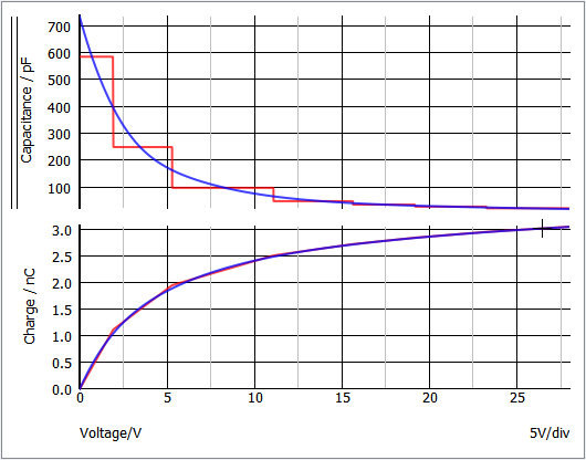
The simulation compares the PWL capacitor charge and capacitance to the curves extracted from the datasheet.
- The capacitance is on the upper graph.
- The red curve is the PWL capacitor
- The blue curve is the datasheet capacitance curve. Important: Notice the capacitance "steps" in the SIMPLIS PWL model.
- The lower curve is the integral of the capacitance; that is, the charge. Important: Notice what may not, at first, be intuitive: the PWL model closely matches the actual charge of the non-linear capacitor, despite the PWL steps in capacitance.