Non-Linear Block (NLB) Multiplier/Dividers
The SIMPLIS Nonlinear Block (NLB) components are primitive components in SIMPLIS which support the modeling of PFC controllers. The NLB components are not intended for general-purpose nonlinear modeling. For alternative multipliers, see the PWM Multipliers and PWL Multipliers topics.
The modeling and the equations used in the NLB components are not compatible with the POP analysis. Hence the POP analysis and the AC analysis, which depends on the successful conclusion of the POP analysis, are both disabled when NLB components are present. Both the PWM Multipliers and PWL Multipliers are compatible with the POP and AC analyses.
The NLB components implement multiply and divide functions. Multipliers and Dividers are available with various input combinations described in the next table. In each model name, NLB_MULTIx_DIVy means the output of the particular component is normally equal to the product of x number of inputs in the numerator divided by the product of y number of inputs in the denominator.
The inputs and output of these multipliers and dividers must be positive with respect to the REF pin. Four quadrant versions of the NLB multiplier can be found here: Non-Linear 4-Quadrant (NLB) Multipliers
In this topic:
| Model Name: | Non-Linear Multiplier/Divider | |
| Simulator: | This device is compatible with the SIMPLIS simulator | |
| Parts Selector Menu Location: |
|
|
| Symbol Library: | SIMPLIS_NLB.sxslb | |
| Model File: | SIMPLIS_NLB.lb | |
| Symbol Names: |
|
|
| Subcircuit Names: |
|
|
| Example Symbol: | 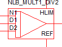
|
|
| Multiple Selections: | Multiple devices can be selected and edited simultaneously. | |
Editing the NLB Multiplier/Divider
To configure the NLB Multiplier/Divider, follow these steps:
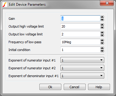
- Double click the symbol on the schematic to open the editing dialog.
- Make the appropriate changes to the fields described in the table below the image.
| Parameter Label | Units | Description |
| Gain | The gain, as applied to the output of the multiplier. | |
| Output high voltage limit | V | The maximum voltage allowed at the output pin. The output is limited to voltages less than this parameter value or the instantaneous voltage on the HLIM pin, which ever is less. |
| Output low voltage limit | V | The minimum voltage allowed at the output pin. The output is limited to voltages greater than this parameter value or the voltage on the REF pin, which is normally zero volts, whichever is greater. |
| Frequency of low-pass filter | Hz | Each NLB block has a low pass filter, with the corner frequency of the filter set by this parameter. |
| Initial condition | V | The initial condition of the output in volts. |
| Exponent of numerator input #n | The exponent applied the nth
numerator input. Each numerator can have exponents of
|
|
| Exponent of denominator input #n | The exponent applied the nth
denominator input. Each denominator can have exponents of
|
Model Details
Each non linear block multiplier/divider have the following attributes:
- Each component has a reference pin, named REF. In most applications, this pin is tied to ground. All input voltages and the multiplier/divider output are defined with respect to this pin.
- There is a resistive input impedance of 10 GΩ between each input pin and the reference pin and there is a resistive output impedance of 50 ohms between the output pin and the reference pin.
- All input signals are defined as the differential voltages of the input pins with respect to the reference pin. The output signal is defined as the differential voltage of the output pin with respect to the reference pin.
- The maximum value of the output is limited to the lower of the following two
values:
- The differential voltage of the HLIM pin with respect to the reference pin.
- The value set to the “Output High Voltage Limit” in the GUI dialog.
- The minimum value of the output is set to the value entered for “Output Low Voltage Limit” in the GUI dialog. This value cannot be negative. Hence, the outputs of all NLB components are restricted to non-negative values. See TODO for a circuit which implements a 4-quadrant multiplier where the output can take on negative values.
- The Gain is applied at the output - effectively gaining the mathematical product/division of the block.
- There is a low-pass filter placed in the output stage of each NLB component. Hence, instantaneous jumps in the input signals will not cause an instantaneous jump in the output voltage.
Two Multiplicand and Two Divisor Example
In addition to the common attributes of all multipliers and dividers, each input signal can be raised to be raised to the power of:
- 0.5
- 1.0
- 1.5
- 2.0
- 2.5
- 3.0
to compute the output voltage For example, if an 2 Multiplicand and 2 Divisor Multiplier is configured as follows:
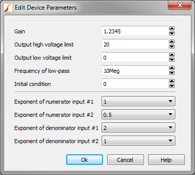
the following mathematical equation is implemented:
\[ \text{1.2345} \times \frac{V_{N1} \times \sqrt{V_{N2}}}{V_{D1}^2 \times V_{D2}} \]
where VN1 and VN2 are the voltage of the “numerator” input pins N1 and N2 with respect to the reference pin, respectively, and VD1 and VD2 are the voltage of the “denominator” input pins D1 and D2 with respect to the reference pin, respectively. Since raising a negative number to non-integral powers is undefined, the signal is considered to be zero when such conditions occur. Hence, in this example, if VN2 is less than zero, the output of the particular NLB component is set to zero
UC3854 Multiplier/Divider
This multiplier/divider implements the multiplier block used in the UC3854 PFC controller.
\[\frac{\left(A-1 \right) \times B}{C^2}\]
The B input of the UC3854 multiplier/divider component corresponds to the IAC input of the UC3854 PFC controller. Although the IAC input of UC3854 is a current-sensing input, the B input of the UC3854 multiplier/divider is a voltage-sensing input like any other input pins in the entire family of NLB components. Hence, the user needs to be aware of such differences in using the UC3854 multiplier/divider component to model any PFC controller similar to the UC3854 controller.
Four Quadrant Multiplier
Four quadrant versions of the NLB multiplier can be found here: Non-Linear 4-Quadrant (NLB) Multipliers
Possible Slow Simulations When Using NLB Multipliers/Dividers
Normally, simulation involving the NLB components would run at simulation speeds typical of a SIMPLIS simulation. The simulation speed time would increase tremendously if one of the “denominator” inputs is either very close to zero, or making either a positive-to-negative transition or a negative-to-positive transition. Proper limiting of the “denominator” inputs may eliminate such a slow simulation.