6.1 Using the Var() and GlobalVar() Functions
In this section of the tutorial, you will modify both a testplan template and a schematic to run a testplan that uses the Var() and GlobalVar() functions to change parameter values.
- Both Var() and GlobalVar() have the same syntax:
- Var(variable_name, value)
- GlobalVar(variable_name, value)
- Both functions write variable statements to the simulator command (F11) window, which is accessed from the schematic by pressing F11; for this reason, the window is commonly referred to as the F11 window. This window appears below the schematic and is used for simulator commands, subcircuit models, variables, etc.
- The only difference between the Var() and GlobalVar() functions is their scope:
- The Var() function parametrizes only the top-level circuit and lower levels of the hierarchy remain unaffected.
- The GlobalVar() function parametrizes at all levels of the hierarchy. While this feature of the GlobalVar() function is convenient, it can be dangerous. The global variables take precedence over any variables defined locally at the hierarchical component level. If you use the GlobalVar() function, make certain the variables being defined are not overwriting any local variables.
- The following guidelines are considered best practices for using these two
functions.
- Make the variable names both explicit and unique.
- Define variables locally whenever possible.
- For additional details about these two functions, see 6.1.3 Completing the Testplan Modifications.
In this topic:
6.1.1 Modifying a Testplan Template
The best approach to creating a customized testplan is to start with one of the built-in testplans as a template.
To create a testplan to demonstrate the first method of changing schematic parameter values, follow these steps:
- Open the built-in sync-buck testplan from SIMPLIS_dvm_tutorial_examples.zip at this path: testplans/dvm_builtin-syncbuck_1in_1out.testplan.
- Remove all but the three Bode plot tests at nominal input voltage; that is, keep
only the first 9 lines:
- The first five comment lines
- The next three lines that each start with Ac
- The next comment line
Note: When you run a built-in testplan, a working copy of the testplan is placed in the same directory as the schematic, making modification easy while maintaining the original testplan. - In rows 6, 7, and 8 in column 5 where the heading is "Label", change Ac Analysis to Default Values.
- Save the testplan as 6.1_my_var_start.testplan.
or
Open the updated testplan saved at this state in SIMPLIS_dvm_tutorial_examples.zip at this path: testplans/6.1_var_start.testplan
The modified testplan should look like the one below with the changes in red.
| 1 | *** | |||||
|---|---|---|---|---|---|---|
| 2 | *** 6.1_var_start.testplan: starting var testplan for DVM tutorial section 6.1 | |||||
| 3 | *** | |||||
| 4 | *?@ Analysis | Objective | Source | Load | Label | |
| 5 | *** | |||||
| 6 | Ac | BodePlot(OUTPUT:1) | Source(INPUT:1, Nominal) | Load(OUTPUT:1, Light) | Default Values|Bode Plot|Vin Nominal|Light Load | |
| 7 | Ac | BodePlot(OUTPUT:1) | Source(INPUT:1, Nominal) | Load(OUTPUT:1, 50%) | Default Values|Bode Plot|Vin Nominal|50% Load | |
| 8 | Ac | BodePlot(OUTPUT:1) | Source(INPUT:1, Nominal) | Load(OUTPUT:1, 100%) | Default Values|Bode Plot|Vin Nominal|100% Load | |
| 9 | *** | |||||
Notes on 6.1_my_var_start.testplan
- The testplan begins with three comment rows, followed by the header row which starts with the special three-character sequence: *?@.
- The rows following the header row consist of three valid Bode plot tests in which the circuit is tested at the nominal input source voltage and for three different load levels (light, 50%, 100%). The values 50% and 100% are interpreted as 50% and 100% of full load, respectively.
- The full load value is stored in the DVM control symbol on the Output page.
- The symbolic value Light represents the lightest load value at which the POP analysis will succeed. This value is also stored in the DVM control symbol on the Output page.
| Header | Value | Description |
| Analysis | AC | Tells the program to expect a valid AC analysis objective in the testplan row. |
| Objective | BodePlot(OUTPUT:1) | Sets the input source to a DC source; sets the first managed load (OUTPUT:1) to a Bode type load; sets the analysis to run a POP and AC simulation; and measures the scalars for gain crossover frequency, gain margin, etc. |
| Source | Source(INPUT:1,value) |
Sets the DC value of the first managed input source (INPUT:1). The nominal, minimum and maximum values are taken from the user entries in the DVM control symbol. The Source(INPUT:1,value) entry does not change the subcircuit definition. |
| Load | Load(OUTPUT:1,value) | Sets the output load as a percentage of full load. The full load value is taken from the DVM control symbol. |
| Label | Varies | A
description of the test with the pipe character (|) as the delimiter.
The label is used to populate the test selection dialog box. Each pipe
character (|) generates a new branch or sublevel in the test
selection dialog. Tests are run in the order in which they appear in the testplan file. Tests are presented in the test selection dialog by an alphanumeric sort of the label values of each test. |
6.1.2 Modifying the Schematic to Use Parameters
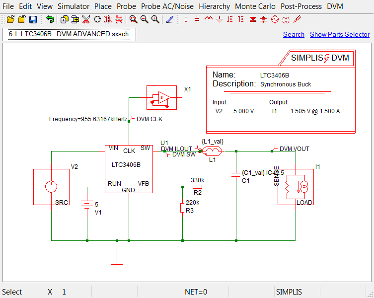
To use the Var() and GlobalVar() statements in a testplan to change parameters, you need a schematic that has components supporting parametrization. This schematic (6.0_LTC3406B - DVM ADVANCED.sxsch) is electrically equivalent to the schematic in section 4.2, but has the inductor replaced with a newer version which accepts parameters.
In the following procedure, you will replace numerical values and units with an expression enclosed in curly braces { }. This syntax signals the program to evaluate the enclosed expression and to return a numeric value that is used for the simulation as if it were entered directly in the Edit Device Parameters dialog.
To parametrize the inductor L1 and the capacitor C1 on the top level schematic, follow these steps:
- Open the schematic from
SIMPLIS_dvm_tutorial_examples.zip
at this path: LTC3406B/6.0_LTC3406B - DVM ADVANCED.sxsch

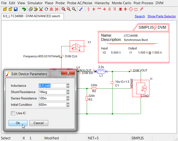
- Double click the inductor L1 to open the Edit Device Parameters dialog.
- Change the Inductance value from 2.2u to {L1_val},
and click Ok.
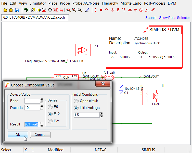
- Double click the capacitor C1.
- Change the Result value from 10u to {C1_val}, and
click Ok.
6.1.3 Completing the Testplan Modifications
Now that you have added the variables L1_val and C1_val to the schematic, you are ready to modify the testplan that you created in 6.1.1 Modifying a Testplan Template.
To complete these modifications, follow these steps:
- Open the testplan that you saved in 6.1.1 Modifying a Testplan Template as
6.1_my_var_start.testplan.
OR
Open the updated testplan from SIMPLIS_dvm_tutorial_examples.zip at this path: testplans/6.1_var_start.testplan. - Insert the following comment after line #9: *** duplicated tests with new test labels
- Copy lines 5-8 from the open testplan, and paste them below the last line of the testplan so that you have six tests.
- In the Label column for each of the three tests in the second set, change
Default Values to New Values. Result: Your testplan should now look like this:
| 1 | *** | |||||
|---|---|---|---|---|---|---|
| 2 | *** modified ( 6.1_var_start.testplan ) | |||||
| 3 | *** | |||||
| 4 | *?@ Analysis | Objective | Source | Load | Label | |
| 5 | *** | |||||
| 6 | Ac | BodePlot(OUTPUT:1) | Source(INPUT:1, Nominal) | Load(OUTPUT:1, Light) | Default Values|Bode Plot|Vin Nominal|Light Load | |
| 7 | Ac | BodePlot(OUTPUT:1) | Source(INPUT:1, Nominal) | Load(OUTPUT:1, 50%) | Default Values|Bode Plot|Vin Nominal|50% Load | |
| 8 | Ac | BodePlot(OUTPUT:1) | Source(INPUT:1, Nominal) | Load(OUTPUT:1, 100%) | Default Values|Bode Plot|Vin Nominal|100% Load | |
| 9 | *** | |||||
| 10 | *** duplicated tests with new test labels | |||||
| 11 | *** | |||||
| 12 | Ac | BodePlot(OUTPUT:1) | Source(INPUT:1, Nominal) | Load(OUTPUT:1, Light) | New Values |Bode Plot|Vin Nominal|Light Load | |
| 13 | Ac | BodePlot(OUTPUT:1) | Source(INPUT:1, Nominal) | Load(OUTPUT:1, 50%) | New Values |Bode Plot|Vin Nominal|50% Load | |
| 14 | Ac | BodePlot(OUTPUT:1) | Source(INPUT:1, Nominal) | Load(OUTPUT:1, 100%) | New Values |Bode Plot|Vin Nominal|100% Load | |
The final step in modifying the testplan is to add two new columns to handle the variables L1_val and C1_val:
- Insert two columns between the columns labeled Objective and S ource.
- In the header row in the column after objective, type this heading: Var(L1_val, 2.2u).
- In the next column, type this heading: Var(C1_val, 10u). Result: The syntax of the Var() function tells the program that the default value for L1_val is 2.2u and the default value for C1_val is 10u.
- For any row in the testplan, DVM interprets an empty field in either of these two new columns as the default value and then writes a .VAR statement with the default value into the F11 window of the schematic for that particular test.
- For any test where the field in either of these two new columns has a value, DVM writes a .VAR statement into the F11 window of the schematic with the exact text entered in the testplan field.
- In the second set of tests (lines 12-15), do the following:
- In the column labeled Var(L1_val, 2.2u), add 1.8u in each in each of those three rows.
- In the column labeled Var(C1_val, 10u), add 12.5u in each in each of those three rows.
The final testplan, with added or changed values in red , now looks like this:
| *** | ||||||
|---|---|---|---|---|---|---|
| *** 6.1_var_final.testplan: final var testplan for DVM tutorial section 6.1 | ||||||
| *** | ||||||
| *?@ Analysis | Objective | Var(L1_val, 2.2u) | Var(C1_val, 10u) | Source | Load | Label |
| *** | ||||||
| Ac | BodePlot(OUTPUT:1) | Source(INPUT:1, Nominal) | Load(OUTPUT:1, Light) | Default Values|Bode Plot|Vin Nominal|Light Load | ||
| Ac | BodePlot(OUTPUT:1) | Source(INPUT:1, Nominal) | Load(OUTPUT:1, 50%) | Default Values|Bode Plot|Vin Nominal|50% Load | ||
| Ac | BodePlot(OUTPUT:1) | Source(INPUT:1, Nominal) | Load(OUTPUT:1, 100%) | Default Values|Bode Plot|Vin Nominal|100% Load | ||
| *** | ||||||
| *** these tests use the new modified values | ||||||
| *** | ||||||
| Ac | BodePlot(OUTPUT:1) | 1.8u | 12.5u | Source(INPUT:1, Nominal) | Load(OUTPUT:1, Light) | New Values |Bode Plot|Vin Nominal|Light Load |
| Ac | BodePlot(OUTPUT:1) | 1.8u | 12.5u | Source(INPUT:1, Nominal) | Load(OUTPUT:1, 50%) | New Values |Bode Plot|Vin Nominal|50% Load |
| Ac | BodePlot(OUTPUT:1) | 1.8u | 12.5u | Source(INPUT:1, Nominal) | Load(OUTPUT:1, 100%) | New Values |Bode Plot|Vin Nominal|100% Load |
You can save your testplan in the schematic directory, or this testplan is available from SIMPLIS_dvm_tutorial_examples.zip at the following path: testplans/6.1_var_final.testplan.
6.1.4 Running the Modified Testplan with the Modified Schematic
Before running this testplan, press F11 to open the simulator command (F11) window in the schematic. As the tests execute, notice the .VAR statements as they are written to and deleted from the F11 window. The entire contents of the F11 window are added to the beginning of the netlist before the simulation starts. After one of the default tests runs, the following variables are displayed in the F11 window:
.VAR L1_val = 2.2u
.VAR C1_val = 10u
6.1.5 Difference Between Var() and GlobalVar
To illustrate the difference between local and global variables, note that if you assign {C1_val} to the capacitor C1 in the op-amp schematic, LTC3406B_EAMP.sxcmp, you get the following error when you run the simulation:
*** ERRORS REPORTED BY SIMPLIS ***
****************************************
<<<<<<< error="" message="" id:="" 1038="">>>>>>>>

input file \LTC3406B\SIMPLIS_Data/6.0_LTC3406B - DVM ADVANCED.deck, line 358:
	C1 6 9 {C1_val} IC=0

A number to represent the value
for `capacitance' is expected at the
location where `{C1_val}' occupies.


*** END SIMPLIS ERROR REPORT ***
This error indicates that the variable {C1_val} was not defined in the netlist for the EAMP subcircuit. To use variables at lower levels of a hierarchical design, you must use the GlobalVar() function. If you change the Var() header entries in 6.1_var_final.testplan to GlobalVar() entries, then {L1_val} and {C1_val} would be available at the top level as well as at all lower levels of the hierarchy. A testplan using the GlobalVar() function looks like this with the modifications in red :
| *** | ||||||
|---|---|---|---|---|---|---|
| *** 6.1_globalvar.testplan: GlobalVar() testplan for DVM tutorial section 6.1 | ||||||
| *** | ||||||
| *?@ Analysis | Objective | GlobalVar (L1_val, 2.2u) | GlobalVar (C1_val, 10u) | Source | Load | Label |
| *** | ||||||
| Ac | BodePlot(OUTPUT:1) | Source(INPUT:1, Nominal) | Load(OUTPUT:1, Light) | Default Values|Bode Plot|Vin Nominal|Light Load | ||
| Ac | BodePlot(OUTPUT:1) | Source(INPUT:1, Nominal) | Load(OUTPUT:1, 50%) | Default Values|Bode Plot|Vin Nominal|50% Load | ||
| Ac | BodePlot(OUTPUT:1) | Source(INPUT:1, Nominal) | Load(OUTPUT:1, 100%) | Default Values|Bode Plot|Vin Nominal|100% Load | ||
| *** | ||||||
| *** these tests use the new modified values | ||||||
| *** | ||||||
| Ac | BodePlot(OUTPUT:1) | 1.8u | 12.5u | Source(INPUT:1, Nominal) | Load(OUTPUT:1, Light) | New Values|Bode Plot|Vin Nominal|Light Load |
| Ac | BodePlot(OUTPUT:1) | 1.8u | 12.5u | Source(INPUT:1, Nominal) | Load(OUTPUT:1, 50%) | New Values|Bode Plot|Vin Nominal|50% Load |
| Ac | BodePlot(OUTPUT:1) | 1.8u | 12.5u | Source(INPUT:1, Nominal) | Load(OUTPUT:1, 100%) | New Values|Bode Plot|Vin Nominal|100% Load |
The above version of the testplan is available from SIMPLIS_dvm_tutorial_examples.zip at this path: testplans/6.1_globalvar.testplan.