Parts Management - Advanced Topics
In this topic:
Associating Multiple Models with Symbols
The previously described procedure for installing model libraries (see Full Model Installation Procedure) explains how to install the library and then, if required, associate each model individually as you place the device on the schematic.
In some situations you might wish to perform the association process in bulk, that is for many devices at once. To so this, use the menu. This is what you will see:
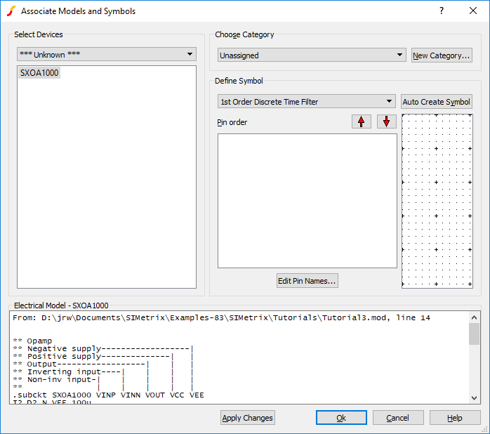
Associate Model Dialog Box
In the top left hand group you select the device or devices that you wish to associate. The drop-down box at the top has a list of categories. Usually you would select a device or devices in the '*** Unknown ***' category but you can also edit the association of known devices in other categories.
Once the category has been selected, a list of devices in that category will be displayed in the list box below. You should then select a device or devices to associate. To select multiple devices hold the control key down while selecting. Note that you will not be allowed to select multiple devices that have different numbers of pins. To help you determine what type of device it is, its electrical model is displayed in the window that covers most of the lower half of the dialog box. You must now define the Category, symbol and, if necessary, the pin order for the device. This is done using the top right hand group of controls titled Choose Symbol/Category. Select an appropriate category and symbol. Note that only compatible symbols that have the same number of pins as the selected device will be shown. If an appropriate symbol is not available, you instruct SIMetrix to create one for you by pressing the Auto Create Symbol button. The symbol created will be functionally correct but of course its design and labelling may not be exactly what you would like. You can edit the pin names of the new symbol by pressing Edit Pin Names... . If other changes are required, you can edit the symbol using the graphical symbol editor at a later time.
The next list box allows the pin order to be changed. If you used the auto create symbol described in the above paragraph, you will not need to change the pin order. Even if you used an existing symbol from the drop down box you probably won't need to change the default as most devices such as opamps and MOSFETs use a de-facto standard pin order. Usually you can check the pin order from the Electrical Model display at the bottom of the dialog box. Many subcircuit definitions are preceded by text which identifies each connection to the sub circuit. This must correspond exactly to the pin order of the symbol. The names of symbol pins and the names used for the subcircuit terminations do not need to match; only the order is important. If the pin order does not match you can change it using the up and down arrow buttons. Simply select a pin in the list box then move it up or down the list. Note that the change will only apply to the device(s) you are currently editing; other devices associated with the same symbol will be unaffected.
Once you have finished selecting the category, symbol and pin mapping you must select the Apply Changes button. Your edits will be lost if you don't, but you will be warned about this before closing the box.
Embedded Association
It is possible to embed association information within the model file itself. This is useful if you wish to prepare a model to distribute to other users and wish to spare them the burden of performing the association process themselves. Models with embedded association can be installed by dropping their files in the command shell with no other action being required.
*#ASSOC Category=category Symbol=symbol [Mapping=mapping]
| category | Category for part. If it has spaces this must be enclosed in double quotation marks. |
| symbol | Internal symbol name to be used for part. |
| mapping | Mapping information. This changes the mapping between the subcircuit terminals and the symbol pin order. Usually, it's easiest simply to arrange the subcircuit pin order to match the symbol pin order in which case this is not required. If however there is some reason why rearranging the subcircuit pins is not desirable, you can instead specify the pin order using the mapping value. The mapping value is a list of symbol pin numbers that match to the corresponding subcircuit terminal. So a mapping value of 2,3,1 says that the first subcircuit terminal connects to pin 2 of the symbol, the second subcircuit terminal connects to pin 3 and the third to pin 1. |
Example
.SUBCKT IRF530 D G S
*#ASSOC Category=NMOS Symbol=nmos_sub
...
.ENDS
Priorities
Its possible that association information could be provided from multiple sources in which case the possibility of conflict arises. If this is the case the following priorities apply:
- User supplied association (e.g. using the associate symbols and models dialog) takes precedence over embedded association.
- Embedded association takes precedence over pre-defined association. Pre-defined association is what is stored in the all.cat catalog file supplied with SIMetrix.
Catalog Files
The data for model and symbol associations are stored in catalog files. There are three catalog files as follows:
| ALL.CAT | Resides in support\devdb under the SIMetrix root directory. Stores catalog data supplied with SIMetrix. SIMetrix never modifies this file. |
| USER_V2.CAT | Resides in devdb/user under the application data directory (see Application Data Directory). Stores catalog data supplied by the user. Data in this file overrides data in ALL.CAT. The Associate Models dialog box writes to this file. In SIMetrix versions 5.2 and earlier this file was called USER.CAT. SIMetrix will automatically import data from USER.CAT to USER_V2.CAT if USER.CAT is present. |
| OUT.CAT | Resides in devdb/working under the application data directory (see Application Data Directory). This is what is actually used by the model library browser to select and place parts. It is generated by the associate model dialog box from information in ALL.CAT, USER_V2.CAT and installed models. It will also be automatically created by the model library browser if it does not already exist. You can also force it to be rebuilt at any time by selecting menu . |
File Format
Catalog files are text files. Each line provides data about a single device in semi-colon delimited fields. The fields are as follows:
| Field 1 | Device name as it appears in browser. This may optionally be followed by a comma followed by the number of terminals for the model. |
| Field 2 | Symbol name |
| Field 3 | Model property - X for subcircuits, as appropriate for other devices. (This field is empty in ALL.CAT and USER_V2.CAT it is determined automatically from electrical model when OUT.CAT is built). |
| Field 4 | Category |
| Field 5 | Sub-category (currently not used) |
| Field 6 | Pin mapping order |
| Filed 7 | Not used |
When you select OK your edits will be written to the USER_V2.CAT file (see above table). This is in the same format as ALL.CAT in the root folder. ALL.CAT is never modified. Also another file is updated called OUT.CAT. This is the file used by the model library browser. The process of building OUT.CAT may take a few seconds if the model library is large.
Importing Models to a Schematic
SIMetrix provides a means to automatically import all models needed for a schematic into that schematic. The models are placed in the simulator command window (opened with F11 see Manual Entry of Simulator Commands). Once the models are imported to a schematic, it will no longer be necessary for SIMetrix to locate the models in the library when a simulation is run. This has the following benefits:
- It makes the schematic completely self-contained. This is useful for archiving or if you wish to pass the schematic to a third party.
- You can edit the models locally without affecting the global library.
| ◄ Parts Management - Configuring the Part Selector | Sundry Topics ▶ |