Periodic Operating Point
Periodic Operating Point (POP) analysis finds a steady-state operating point of switched systems that are periodically driven or self-oscillating. The predominant application of this analysis mode is to rapidly find the settled condition of a switching power supply without having to simulate the entire power-up sequence. This dramatically speeds up the analysis of the design behavior under different load conditions.
A POP analysis requires a trigger signal to indicate the start of each periodic cycle. You have two methods to add this trigger to your schematic.
- The best method is to use a special schematic part by following these steps to place
the trigger on your schematic:
- If the parts selector is not shown, select from the menu bar.
- Click the arrow to open the Commonly Used Parts category.
- Select POP Trigger from the bottom of the list.
- The other method is to specify a full part reference of the device in the Choose Analysis... dialog box as noted in step 3 of Setting up a POP Analysis.
-
Note: This is needed only when the schematic hierarchy is converted to an ASCII text model. SIMPLIS cannot find the schematic symbol in a model which has been reduced to an ASCII text definition.
For more information about POP analysis, see the SIMPLIS Reference Manual ().
Setting up a POP Analysis
- From the menu bar, select
- Check POP in the Select analysis section on the right side of the dialog box.
- Click the Periodic Operating Point tab, and then enter the values which are
shown explained below.
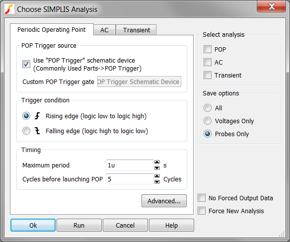
Parameter Description POP Trigger source - Use "POP Trigger" Schematic Device POP analysis requires a trigger signal to indicate the start of each periodic cycle. The best way to define this is using a special schematic part. Trigger gate If you do not check the option above to use the schematic POP trigger device, you must specify a suitable part in this field by entering the full part reference of the device. Trigger Condition The polarity of the trigger edge as specified by the following two parameters. Maximum period You should set this to a value that is larger than the expected switching cycle, but it should be less than twice the expected switching cycle to prevent unintentional POP convergence on a sub-harmonic oscillation. Note: During each run, SIMPLIS expects to see valid trigger conditions. However, if there is a fault in the design of the circuit or a fault in the definition of the trigger conditions, it is possible that none will be detected. The maximum period parameter prevents SIMPLIS from carrying on indefinitely in such an event.Cycles before launching POP Number of cycles to run before SIMPLIS starts the POP analysis.
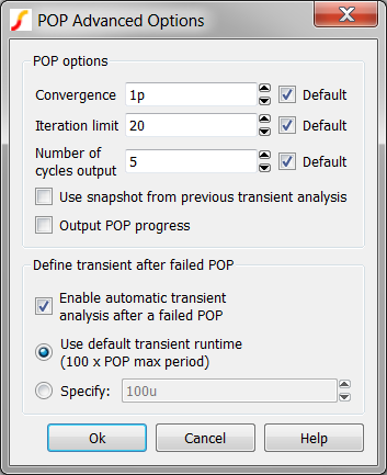
Advanced Options
The Advanced... button on the Periodic Operating Point tab of the Choose Analysis Dialog brings up the following dialog, allowing you to set various POP options and to define a transient analysis after a POP failure as shown in the POP Advanced Options dialog box.
| Parameter | Description |
| Convergence | Sets the convergence criteria for the periodic operating point analysis. The convergence criteria is satisfied when the relative change in each state variable, between the start and end of a switching cycle, is less than this parameter. All state variable must have a relative change lower than the convergence criteria for the POP run to converge. This parameter is expressed in percent. |
| Iteration limit | Sets the maximum number of iterations for the periodic operating point analysis. |
| Number of cycles output | After a successful POP analysis, and if there is no transient analysis specified, SIMPLIS will generate the steady-state time-domain waveforms for an integral number switching cycles. This option sets the number of cycles to output and can be between 1 and 16. |
| Use snapshot from previous transient analysis | If checked, POP is instructed to take advantage of the last data point of a previous transient simulation, assuming the circuit and the initial conditions remained the same between the two simulation runs. |
| Output POP progress | If checked the progress of the POP solution will be output to the data file for plotting and subsequent debugging. |
| Define transient after failed POP | If a POP analysis fails to converge, you have the option to automatically start a subsequent transient analysis. This is useful to help diagnose the cause of the POP failure. |
| Enable automatic transient analysis after a failed POP | Check this box to enable this feature. The transient analysis will run for 100 x POP period by default. To change this, click on Specify then enter the desired period. |
For more information about the advanced POP options, see the Advanced SIMPLIS Training Course: 2.3.2 The Core POP Process.