SystemDesigner Gain
The SystemDesigner Gain models an amplification of a bus value. The Gain can be any integer greater than 1.
The propagation delay can be defined as a fixed time, as asynchronous to any clock, or as a synchronous delay where the delay is a number of SystemDesigner -clocks cycles. In this release of SystemDesigner , the synchronous delay is supported only for integer-sampled data simulations.
In this topic:
| Model Name: | SystemDesigner Gain | |||
| Simulator: | This device is compatible with the SIMPLIS simulator. | |||
| Parts Selector Menu Location: | SystemDesigner Functions (max. 32 bit) | |||
| Symbol Library: | SIMPLIS_SystemDesigner.sxslb | |||
| Model Library: | SIMPLIS_SystemDesigner.lb | |||
| Subcircuit Name: | SIMPLIS_SD_GAIN_32 | |||
| Symbol: |
|
|||
| Multiple Selections: | Only one device at a time can be edited. | |||

Editing the SystemDesigner Gain
To configure the SystemDesigner Gain, follow these steps:
- Double click the symbol on the schematic to open the editing dialog to the Parameters tab.
- Make the appropriate changes to the fields described in the table below the image.
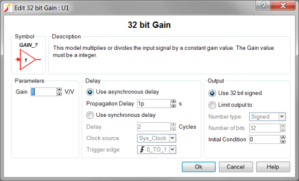
| Label | Parameter Description |
| Gain | The gain constant. The gain can be any signed 32 bit integer. |
| Use asynchronous delay | Implements a combinatorial model where the output voltage changes in response to the input voltage change after a propagation delay. |
| Propagation delay | The propagation delay from an input change to an output change in seconds. This parameter is used only in models with Asynchronous delay. |
| Use synchronous delay | In response to an input voltage change, the output voltage changes after a designated number of clock cycles. |
| Delay | The propagation delay from an input change to an output change in number of clock cycles. The output will not change until the number of clock cycles has been reached. The output will then change state only on the selected Clock source edges specified by Trigger edge. This parameter is used only in models with Synchronous delay. |
| Clock source | Specifies the global clock used for the Gain. The Clock can be set up using the SystemDesigner->Edit SystemDesigner Clocks... menu item or by placing a Start of Conversion Breakin. |
| Trigger edge | Sets the Gain output to change on specific edges of the Clock:
|
| Use asynchronous delay | Implements a combinatorial model where the output voltage changes in response to the input voltage change after a propagation delay. |
| Propagation delay | The propagation delay from an input change to an output change in seconds. This parameter is used only in models with Asynchronous delay. |
| Use synchronous delay | In response to an input voltage change, the output voltage changes after a designated number of clock cycles. |
| Delay | The propagation delay from an input change to an output change in number of clock cycles. The output will not change until the number of clock cycles has been reached. The output will then change state only on the selected Clock source edges specified by Trigger edge . This parameter is used only in models with Synchronous delay. |
| Clock source | Specifies the global clock used for the Gain. The Clock can be set up using the SystemDesigner->Edit SystemDesigner Clocks... menu item or by placing a Start of Conversion Breakin. |
| Trigger edge | Sets the Gain output to change on specific edges of the Clock:
|
Examples
The SystemDesigner Gain is used in numerous examples: