Managed Sources and Loads
As described in Introduction to DVM, managed-source and managed-load symbols can represent any number of different electrical definitions, depending on the test objective of a particular simulation. While the source and load symbols do not visibly change, the electrical definition of the subcircuit called by the symbol does change.
For example, DVM can change the subcircuit used by a managed load symbol to do the following:
- Represent a simple load resistor
- Exhibit special transient behavior, such as change a pulsed load to simulate a load transient
- Include an injected AC source and the Bode plot probe required for measurement in an AC Bode plot analysis
Likewise, a managed source subcircuit can do these things:
- Represent a constant DC voltage source
- Represent a start-up ramp or a pulsed line voltage source
- Perform input impedance measurements by including components that inject an AC small signal perturbation into the circuit and measure the resulting input impedance
Configuring DVM Sources and Loads
You define which sources and loads are managed using the SIMetrix/SIMPLIS DVM Control Panel that opens when you double click on the DVM control symbol.
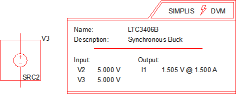
After selecting the sources and loads to manage, the reference designators (V2, I1, in this example) are saved to the DVM control symbol. You then need to edit the default specifications for the managed sources and loads. For more information, see the DVM Tutorial 3.1 Editing the Schematic topic.
Custom subcircuits can be designed as schematic components and then converted to ASCII models to be used with DVM.
Adding a New DVM Source or Load
Adding a source is described here, but the process of adding a load is exactly the same. The design starts with V2 and I1 as the source and load reference designators.
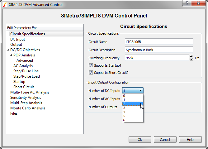
- Select the number of new sources and loads from the Circuit Specifications page of
the control symbol dialog. For this example, select 2 from the Number of DC
Inputs drop-down menu.
 Result: The page selection box on the left side is populated with two DC input source entries:
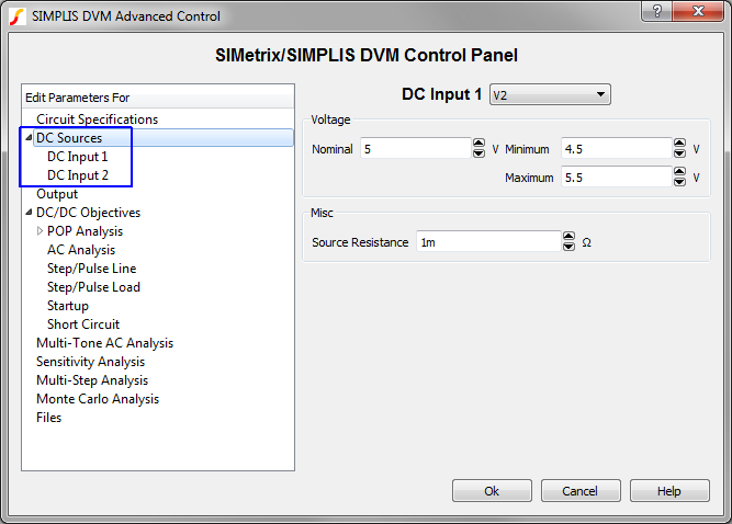
- Select the second DC input source and enter the source voltage and resistance
parameters.
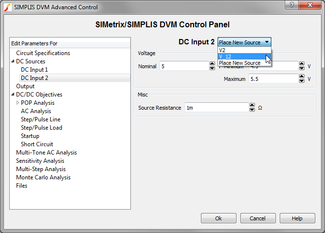
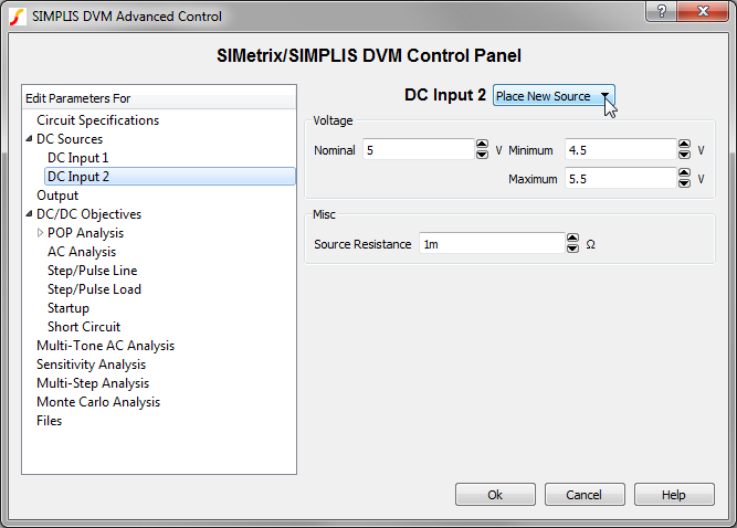 Note: DVM automatically finds all DVM input source and load symbols and if you have already placed a source or a load symbol, you can select the reference designator from the drop-down box shown above. Otherwise, DVM automatically enters a source/load placement routine after you accept the dialog in the next step.
 - After entering the parameters, click Ok to accept the dialog. Result: DVM has detected that you wish to add a source to the design. A messagebox opens alerting you to this:
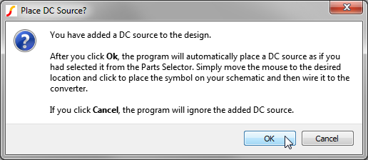
- Click Ok, and place the new input source on the schematic. Result: DVM adds the source information to the control symbol:
Adding an Existing DVM Source or Load
If you have already placed a DVM source or load on the schematic, you can easily add it to the DVM managed sources or loads. In this example, assume that reference designator V_12 was already palce on the schematic and you want to manage this source also.
- Double click on the control symbol...
- Select the new number of sources to be 2:
- On the DC Input 2 page, select the V_12 reference designator:
- Click Ok.
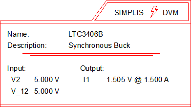
Result: The control symbol now lists both the V2 and V_12 designators.
Removing Managed Sources or Loads
To remove a managed source or load, follow these steps:
- Double click on the DVM control symbol.
- In the page-selection box, select the source or load that you want to remove.
- Click Circuit Specifications, and change the number of inputs or outputs.
- Click Ok to save the new specifications.
Changing a Source or Load Subcircuit Definition
You change a source or load subcircuit definition using the Source and Load testplan entries.