Multi-Level Parameterized Opamp (Version 8.0+)
The Multi-Level Parameterized Operational Amplifier has two levels: 1 and 2. Level one models an idealized operational amplifier where both the gain-bandwidth product and the output characteristics are idealized. Level two adds output limiting on both the source and sink currents and the saturation voltages, as well as slew rate limiting and gain-bandwidth product. The level two model has dominant pole feedback with a single pole, there are no high frequency poles.
In this topic:
| Model Name: | Multi-Level Parameterized Opamp | |||||||||||||||
| Simulator: | This device is compatible with both the SIMetrix and SIMPLIS simulators. | |||||||||||||||
| Parts Selector Menu Location (SIMetrix): | ||||||||||||||||
| Parts Selector Menu Location (SIMPLIS): | ||||||||||||||||
| Symbol Library: | analog.sxslb | |||||||||||||||
| Model File (SIMetrix): | generic.lb | |||||||||||||||
| Model File (SIMPLIS): | simplis_opamp.lb | |||||||||||||||
| Symbol Name: | OPAMP_PARAM_V8 | |||||||||||||||
| Subcircuit Name: | PARAM_OPAMP | |||||||||||||||
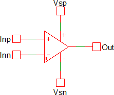
| Symbol: |
|
|||||||||||||||
| Multiple Selections: | Multiple devices can be selected and edited simultaneously. | |||||||||||||||
Previous Version Compatibility
This symbol and editing dialog was introduced with version 8.0. While the model will simulate in versions prior to Version 8.0, the parameters will not be editable with the double click pop-up dialog.
For a opamp compatible with versions prior to version 8.0, see the parts selector entry:
Obsolete | OpAmps | Multi-Level Parameterized Opamp (Obsolete)
The obsolete opamp symbol uses the same electrical model but with a different symbol and editing dialog.
Symbol Migration
Symbols placed on schematics in previous versions of SIMetrix/SIMPLIS can be automatically migrated to use the new symbols. The schematic tools menu will invoke a routine which migrates the existing symbols to the new symbols. As this action makes substantial changes to the schematic, it is recommended that you save a backup copy of the schematic first.
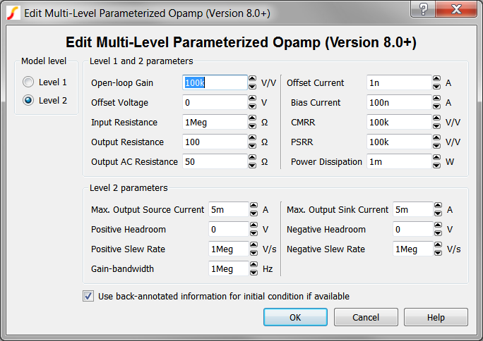
Editing the Multi-Level Parameterized Opamp
To configure the Multi-Level Parameterized Opamp, follow these steps:
- Double click the symbol on the schematic to open the editing dialog.
- Choose a model level, and then make the appropriate changes to the fields described in the table below the image.
Parameters used in both Level 1 and Level 2 Models
| Parameter Label | Units | Description |
| Open-loop gain | V/V | Vout/(Vin+ - Vin-) - not in dB |
| Offset Current | A | Difference between input currents when out=0 |
| Offset Voltage | V | Input voltage needed for zero output |
| Bias Current | A | Average of input currents when out=0 |
| Input Resistance | Ω | Differential input resistance |
| Output Resistance | Ω | Series output resistance |
| Output AC Resistance | Ω | AC output resistance. This resistance must be less than the Output Resistance parameter. |
| CMRR | V/V | Common mode rejection ratio. Expressed as straight ratio - not in dB |
| PSRR | V/V | Power supply rejection ratio. Expressed as straight ratio - not in dB |
| Power Dissipation | W | Quiescent current is defined differently for the SIMPLIS and SIMetrix versions. In the SIMetrix version it is a constant current and does not vary with supply voltage. In the SIMPLIS version it is implemented as a resistance that is calculated to draw the specified current for a 15 volt supply rail. |
Parameters used in Level 2 Models
| Parameter Label | Units | Description |
| Max. Output Source Current | A | Maximum current sourcing capability of the output |
| Max. Output Sink Current | A | Maximum current sinking capability of the output |
| Positive Headroom | V | Difference between positive supply voltage and maximum output voltage |
| Negative Headroom | V | Difference between min output voltage and negative supply voltage |
| Pos. Slew Rate | V/s | Slew rate for positive output transitions |
| Neg. Slew Rate | V/s | Slew rate for negative output transitions |
| Gain-bandwidth | Hz | Gain-bandwidth product |
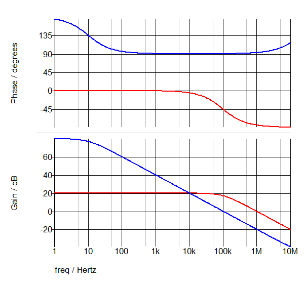
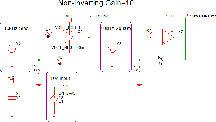
Example - Frequency Response
The test circuit used to generate the waveform examples in the next section can be downloaded here: simplis_006_param_opamp_non_inv_freq_response.sxsch.
Waveforms
The opamp is configured as a non-inverting gain of 20dB. With an open loop gain of 100 dB and a Gain crossover frequency of 1MHz, the overall gain of the opamp is 20dB at low frequencies, with a pole at 100kHz, and a 1MHz unity gain crossover frequency. The loop gain pictured in blue has the expected maximum of 80dB and the unity gain crossover frequency is 1MHz.
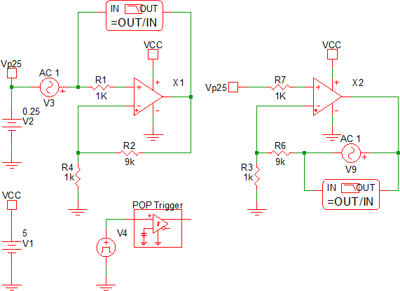
Example - Saturation and Slew Limit
The test circuit used to generate the waveform examples in the next section can be downloaded here: simplis_006_param_opamp_output_sat_slew_rate_limit.sxsch.
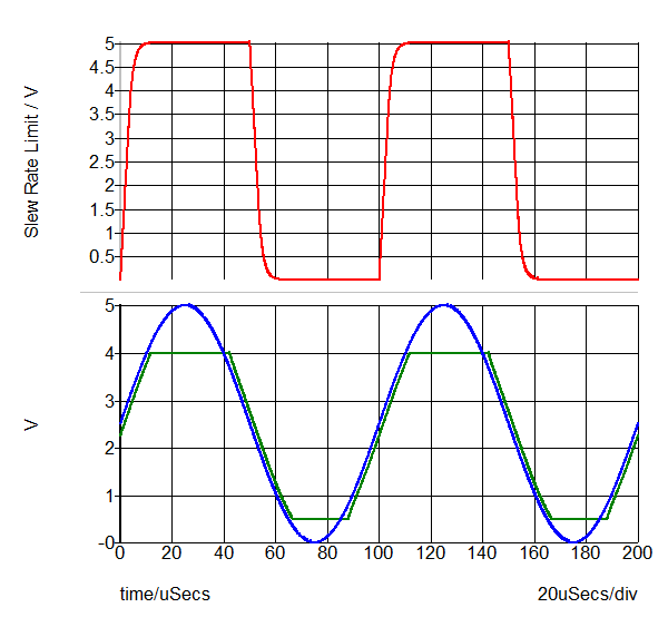
Waveforms
The slew rate limited behavior of the opamp is shown on the upper axis. This opamp has the positive and negative headroom set to 0V, meaning the output can swing from rail-to-rail which in this circuit is 0 to 5V.
The output limiting characteristics of the opamp are shown in the lower axis. The input signal is gained by 10 using a VCVS and is displayed as the blue curve. The opamp output, which is sligtly phase shifted and clamped is shown in green. The positive headroom is set to 1V and the negative headroom is set to 500mV.