LoadTrAC() Test Objective
The purpose of the LoadTrAC test is to verify that the output voltage is within regulation; unlike the DC/DC PulseLoad() objective, this test uses timing in terms of AC line cycles and the actual phase angle of the source. The input is configured as a AC Fixed Input Source, and the output is configured as a Pulse Load - Single Current Pulse.
The initial, pulse, and final current values are passed as arguments to the LoadTrAC() function. The initial conditions for the simulation are typically found with a FindAcSteadyState() test, which runs a long transient simulation and saves the initial conditions using the GenerateInitFile testplan entry.
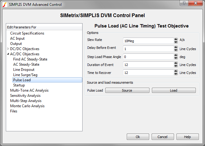
The LoadTrAC() test objective runs a transient simulation on the converter with the timing based on values entered in the Pulse Load page, which is shown below and accessed from the Full Power Assist DVM control symbol.
This test objective measures the following scalar values:
- Frequency of Input Source
- Per Line Cycle Average of each output load voltage at:
- The start of the simulation
- The last line cycle of the simulation
- The second-to-the-last line cycle
- Percentage change in output load voltages over the final two line cycles
In this topic:
Testplan Syntax
The LoadTrAC() function has the following syntax with the arguments described in the table below:
LoadTrAC(REF, ISTART, IPULSE, IFINAL, FREQUENCY)
LoadTrAC(REF, ISTART, IPULSE, IFINAL, FREQUENCY, OPTIONAL_PARAMETER_STRING)
| Argument | Range | Description |
| REF | n/a | The actual reference designator of the DVM Load or the generic syntax of OUTPUT:n where n is an integer indicating a position in the list of DVM loads. |
| I START | min: 0 | The starting current for the load. This can be a numeric value or a symbolic value, such as a percentage of full load. |
| I PULSE | min: 0 | The pulse current for the load. The pulse current can be a numeric value or a symbolic value, such as a percentage of full load. |
| I FINAL | min: 0 | The final current for the load. This can be a numeric value or a symbolic value, such as a percentage of full load. |
| FREQUENCY | min: > 0 | The AC line frequency of the input source. This is used to both set the frequency of the input source and to set the simulation timing. The FREQUENCY can be a numeric or a symbolic value, such as F_High or F_Low. |
| OPTIONAL_PARAMETER_STRING | n/a | Parameter string with a combination of one or
more timing parameters:
|
parameter_name1=parameter_value1 parameter_name2=parameter_value2The order of the parameter key-value pairs does not matter.
Simulation Timing
DVM sets the timing parameters for the LoadTrAC() test objective based on values that you enter on the Pulse Load page of the DVM Full Power Assist control symbol:
Delay Before Event, Duration of Event, Time to Recover, Step Load Phase Angle, and Slew Rate
In the OPTIONAL_PARAMETER_STRING and in the calculations below, these values are renamed as follows:
- NCYCLES1 = Delay Before Event
- NCYCLES2 = Duration of Event
- NCYCLES3 = Time to Recover
- PHASE_ANGLE = Step Load Phase Angle
- SLEW_RATE = Slew Rate
The time delay is based on the following conditions and calculations. Typically the LINE_PHASEANGLE is set to 0, although in a 3 phase system only one of the three line sources will have a zero LINE_PHASEANGLE.
If LINE_PHASEANGLE is greater than 0, then
\[ \text{TIME_DELAY} = \frac{360 - \text{LINE_PHASEANGLE}}{360 * \text{FREQUENCY}} + \frac{\text{NCYLES1}}{\text{FREQUENCY}} + \frac{\text{PHASE_ANGLE}}{360 * \text{ FREQUENCY}} \]
If LINE_PHASEANGLE is less than or equal to 0, then
\[ \text{TIME_DELAY} = \frac{\text{NCYLES1}}{\text{FREQUENCY}} + \frac{\text{PHASE_ANGLE}}{\text{360} * \text{FREQUENCY}} \]
The rise time, pulse width, fall time, and stop time are based on these calculations:
\[ \text{RISE_TIME} = \frac{ abs \left( I_{PULSE}-I_{START} \right)}{\text{SLEW_RATE}} \]
\[ \text{PULSE_WIDTH} = \frac{\text{NCYLES2}}{\text{FREQUENCY}} \]
\[ \text{FALL_TIME} = \frac{ abs \left( I_{PULSE}-I_{FINAL} \right)}{\text{SLEW_RATE}} \]
\[ \text{STOP_TIME} = \frac{\text{NCYCLES1} + \text{NCYCLES2} + \text{NCYCLES3}}{\text{FREQUENCY}}\]
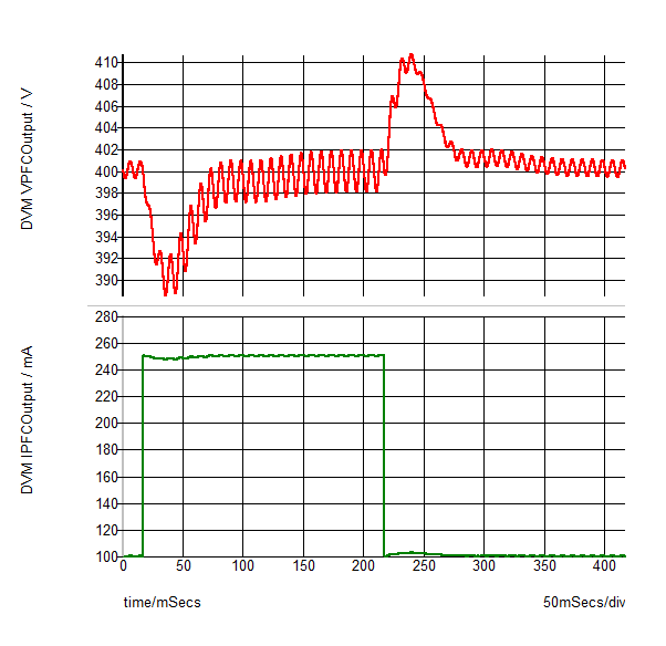
A typical output waveform from this test objective is shown on the graph below:
Source and Load Subcircuit Configuration
The LoadTrAC() test objective sets the source and load subcircuits to the following:
| Source | Control Source (if used) | Load |
| AC Fixed Input Source | DC Auxiliary Source | Pulse Load - Single Current Pulse |
Loads other than the output under test are set to the Resistive Load. All other sources are set to either the DC Input Source for DC sources or the AC Fixed Input Source for the AC input sources.
Measured Scalar Values
The LoadTrAC() test objective measures the following scalar values where {load_name} is the name assigned to each load, and {source_name} is the name assigned to each source.
| Scalar Name | Description |
| Frequency({source_name}) | A number which represents the line frequency. |
| V{load_name}%_diff_last_2_linecycles | The percent change in the output voltage when averaged over the last two line cycles. |
| vout{n}_recovery_time_rising | The time it takes for the converter to recover the output voltage to within the output voltage specifications after the rising edge of the pulse. |
| vout{n}_recovery_time_falling | The time it takes for the converter to recover the output voltage to within the output voltage specifications after the falling edge of the pulse. |
| V{load_name} Last LineCycle | The average value of the output voltage during the last line cycle in the simulation. Used for the V {load_name} %_diff_last_2_linecycles calculation. |
| V{load_name} Previous LineCycle | The average value of the output voltage during the second to the last line cycle in the simulation. Used for the V {load_name} %_diff_last_2_linecycles calculation. |
| I{load_name} | Minimum and Maximum values of the load current. |
| V{load_name} | Minimum and Maximum values of the load voltage. |
| I{source_name} | Minimum and Maximum values of the source current. |
| V{source_name} | Minimum and Maximum values of the source voltage. |
Measured Specification Values
In the following table, {load_name} is the name assigned to each load. The default value is LOAD. DVM forces each load name to be unique so that the scalar and specification values for each load are unique.
| Scalar Name | PASS/FAIL Criteria |
| AC_Settling({load_name}) | The percentage change in the output load voltage over the final two line frequency cycles is less than the maximum specification value. |
| Max_V{load_name} | The maximum value of the output during the simulation time is less than the maximum specification value. |
| Max_V{load_name}_overshoot | The maximum overshoot value of the output during the simulation time is less than the overshoot specification value. |
| Min_V{load_name} | The minimum value of the output during the simulation time is greater than the minimum specification value. |
Testplan Example
An example of the LoadTrAC() test objective taken from the AC/DC (1-input/1-output) testplan is shown below. This test objective configures the load to pulse from the Light to the 100% load symbolic values. Both values are defined on the Output page of the Full Power Assist DVM control symbol. The timing of the pulse load event will be determined by the values on the Pulse Load page of the Full Power Assist DVM control symbol.
| *?@ Analysis | Objective | Source | Load | Label | GenerateInitFile | IncludeInitFile |
| Transient | LoadTrAC(OUTPUT:1, Light, 50%, Light, F_Low) | AcFixed(INPUT:1, LL, Nominal, F_Low) | Transient|LoadTrAC|LL_Nominal|F_Low|Light Load to 50% Load to Light Load | INITFILE_LL_Nominal_F_Low_Light Load |
Optional Parameter String
The following LoadTrAC() test objective uses the OPTIONAL_PARAMETER_STRING argument to set the output load to pulse between the Light and 100% load symbolic values and sets the pulse time delay (NCYLES1) to 2 line cycles, and the pulse duration to 10 line cycles.
LoadTrAC(OUTPUT:1, Light, 50%, Light, F_Low, NCYCLES1=2 NCYCLES2=10)
Test Report
You can view the complete test report in a new browser window here: LoadTrAc() Test Report. Below is an interactive link to the same test report.